Electrolysis Assisted Biomass Gasification for Liquid Fuels Production
 Sennai Mesfun
 Klas Engvall
 Andrea Toffolo3
- 1RISE Research Institutes of Sweden, Stockholm, Sweden
- 2School of Chemical Science and Engineering, KTH, Stockholm, Sweden
- 3Department of Engineering Science and Mathematics, Energy Science Division, Luleå University of Technology, Luleå, Sweden
Gasification is a promising pathway for converting biomass residues into renewable transportation fuels and chemicals needed to comply with the ambitious Swedish environmental targets. The paper investigates the integration of a molten carbonate electrolysis cell (MCEC) in biofuel production pathway from sawmill byproducts, to improve the performance of gas cleaning and conditioning steps prior to the final conversion of syngas into liquid biofuels. The energy, material, and economic performance of process configurations with different gasification technologies are simulated and compared. The results provide relevant information to develop the engineering of gas-to-liquid transportation fuels utilizing renewable electricity. The MCEC replaces the water-gas shift step of a conventional syngas conditioning process and enables increased product throughput by as much as 15%–31%. Depending on the process configuration and steam-methane reforming technology, biofuels can be produced to the cost range 140–155 €/MWh in the short-term.
1 Introduction
Electrification of the transportation fleet is growing and considered as one of the best options to transition from fossil-based fuels, especially for passenger vehicles where its share has increased at a promising rate. Nonetheless, the role of biofuels cannot be overlooked given the varying nature of the transportation mode, such as heavy-duty trucks, aviation and marine where the need for carbon neutral substitution will remain for the foreseeable future. Thus, biofuels are expected to allow the achievement of Sweden’s national targets for a fossil free vehicle fleet in 2030 and a carbon neutral society in 2045. Sweden is endowed with a vast forest coverage making it a major forest industry nation with production capacities of about 18.4 million cubic meters of sawn wood (Eurostat 2018b) and 8.6 million tonnes of pulp (Eurostat 2018a) in 2018. The Swedish forest industry can benefit from timely evaluation and knowledge of emerging technologies in the biofuel arena. Early identification value chains with high resource effectivity, favorable economic feasibility and least carbon footprint can facilitate deployment of commercial scale production of biofuels in the short term.
Power-to-gas and power-to-liquid technologies, based on electrolysis, to store intermittent renewable energy in the form of chemical fuels are progressively evaluated (Hulteberg and Karlsson 2009; Clausen et al., 2010; Chen et al., 2014; Giglio et al., 2015; Koytsoumpa et al., 2016; Mesfun et al., 2017; Mesfun et al.,2019), including, for example, the techno-economics of hydrogen (Hulteberg and Karlsson 2009), methanol (Clausen et al., 2010) and methane (Mesfun et al., 2019; Monzer et al., 2021) production (Ferrario et al., 2021). investigated MCEC application for offgas recovery system in a steam-reforming process at oil refinery. Electrolyzers for these purposes can be classified in accordance with their operating temperature (Wang et al., 2019), where low temperature electrolyzers, based on Polymer Electrolyte Membrane (PEM) and alkaline technologies, are the most common (Schalenbach et al., 2018). At higher temperatures, solid oxide electrolysis cell (SOEC) and molten carbonate electrolysis cell (MCEC) electrolyzers are the possible choices (McPhail et al., 2011). Electrolysis at high temperature has several advantages, generally less energy intensive since part of the electrical energy needed to decompose the water molecule is replaced by the heat (Hu 2016), processing of hydrocarbon fuels with minor degradation of catalyst (Giulio and Nam, 2012), and the possibility to operate in reverse mode producing electricity (Mcphail et al., 2015). Neither the SOEC nor the MCEC technology is commercial today and heavily relies on R&D efforts to commercialize solid oxide fuel cell (SOFC) (Küngas 2020) and MCFC (Barckholtz et al., 2021; Ferguson and Tarrant 2021; Monzer et al., 2021; Shikhar et al., 2021) where MCFC units of up to 3.7 MW are sold on the market and used in several power plants (10–60 MW) worldwide (Bove et al., 2008). In view of using high temperature electrolysis technology in applications utilizing CO2 for co-electrolysis of CO2 and H2O in CO2-rich streams, the MCEC technology is favored due to the highly solubility of CO2 in the molten carbonate electrolytes (Chery et al., 2015). All things considered, MCEC is the preferred choice of technology in applications for upgrading and utilizing the product gas produced from biomass gasification.
Biomass gasification is considered a strategic technology for converting residues from forest industry to transportation fuels, chemicals, or electricity. A significant challenge in biomass gasification is the engineering of an efficient product gas cleaning and conditioning process before utilizing the produced synthesis gas in catalytic upgrading to biofuels. Thus, it is essential to find ways to improve the performance of syngas conditioning processes. In a previous study (Mesfun et al., 2019), we evaluated the techno-economic potential of integrating MCEC technology in a dual fluidized bed gasification system for bio-SNG production. The MCEC was integrated in the cleaning and conditioning process to reform hydrocarbons in the gas and to boost the production of a tailored syngas prior to bio-SNG production utilizing intermittent renewable power. The results from the study indicate that the production of SNG can be boosted by approximately 50%–60% without the need of an additional carbon source. The study also demonstrated how MCEC could be utilized in a power-to-gas process, enabling a greater share of intermittent renewable power into the energy supply system. In the present work, we evaluate the potential for converting sawmill byproducts to sustainable aviation fuel (SAF) onsite, using gasification technology enhanced by MCEC. The aim is to investigate the capability of MCEC technology to boost the production of renewable transportation fuels via gasification of woody biomass, gas conditioning, in which the MCEC essentially replaces the water gas shift reactor, and a Fischer Tropsch (FT) synthesis process. FT process is one of the ASTM approved pathways for SAF production and is therefore the most relevant conversion technology for the conceptual process addressed here. Previous studies about production of transportation liquid fuels consider conventional integration of gasification and FT technologies, see e.g., (Baliban et al., 2013; Kim et al., 2013; Trippe et al., 2013; Niziolek et al., 2014; Ail and Dasappa 2016). Others looked at benefits of integrating gasification, electrolysis and FT process (Li et al., 2016; Chen et al., 2017; Stempien et al., 2015). A handful of studies also consider the integration of either electrolysis or co-electrolysis with gasification and FT (Samavati et al., 2017, Samavati et al.,2018a; Samavati et al., 2018b; Hillestad et al., 2018). There is no mention of biomass to liquid concepts enhanced with MCEC in the literature.
Process simulations developed in UniSim Design (interfaced with MATLAB Simulink for the simulation of MCEC performance) were used to evaluate the energy efficiency, the yields and the economic indicators of different process configurations for integrated SAF production at a sawmill facility. The process configurations are characterized by three different gasification technologies (indirectly heated dual fluidized bed, directly heated bubbling fluidized bed and the WoodRoll process) and by two types of reactors reforming methane and light hydrocarbons into CO and H2 upstream the MCEC (traditional steam reformer and electric resistance heated steam reformer).
The paper presents an overview of the processes and technologies considered for SAF integrated production at a sawmill site (Section 2), a description of the methodology used to evaluate the performance of the different process configurations (Section 3), a comparison of the results obtained from process simulations (Section 4), which are discussed in Section 5, and finally the conclusions (Section 6).
2 Processes and Technologies
Figure 1 illustrates the schematic of a process configuration for transportation fuel production from biomass gasification, including primary gas cleaning, an integrated MCEC process and final trace gas cleaning. Starting from left, the process consists of 1) a biomass gasifier; 2) a primary gas cleaning step, including removal of particle, tar and other impurities (H2S, etc.) to concentration levels as specified by the MCEC; 3) the MCEC process, together with a CO2/O2 separation unit; 4) a final gas cleaning step for removal of e.g., trace elements; 5) a chemical synthesis process. The focus of this work is on the MCEC as the key technology introduced in the process configuration. Unlike other types of electrolysis technologies that require pure stream of water/steam (e.g., PEM, alkaline), the MCEC can utilize streams with a wider variety of species, such as the product gas from a gasification process. The MCEC allows for a certain degree of hydrocarbon reforming, H2/CO ratio conditioning via WGS and carbon dioxide separation from the product gas in one process step. Another advantage is the production of oxygen that can be used in the gasification process, enabling the use of gasification technologies in which air separation would be needed for syngas production. Nevertheless, there are limitations for the concentration of tar and other impurities at MCEC inlet (Section 2.1) and, therefore, the primary gas cleaning process configuration could vary depending on the biomass feedstock and gasification technology selected. The raw product gas from a gasifier undergoes several process steps of gas cleaning and upgrading to achieve tar and particulates-free syngas stream. The primary cleaning process is comprised of a hot gas cleaning step to remove particles that follow the gas. Depending on the gasification technique, hydrocarbons, tar, and impurities that can harm the electrochemical unit must be removed. This can be performed using e.g., a RME scrubber or a catalytic tar reformer (Guan et al., 2016).
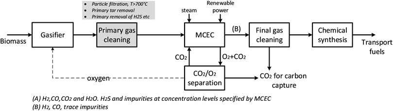
FIGURE 1. Schematic of a process configuration for transportation fuel production from biomass gasification, including a MCEC process step.
Figure 2 shows a simplified block diagram of the process configuration investigated in this study (a more detailed process flowsheet is presented in the Supplementary Material). The main difference from Figure 1 is the introduction of a reformer before the MCEC, motivated by the following two reasons. First, the syngas after hot gas cleaning may contain tar and hydrocarbons such as methane, C2Hx (ethyne, ethylene and ethane) and benzene, which significantly reduce the overall carbon conversion from biomass to finished products when left unutilized. Initial evaluations were made to investigate potential reforming activity in the MCEC by supplying a syngas containing methane 3–8% vol. at temperatures 700–800°C. The equilibrium results indicated that methane reforming was lower than expected, and a significant amount of methane was present at the cathode. Second, the Fischer Tropsch synthesis (the considered chemical synthesis process) produces a tail-gas rich in light-hydrocarbon components (C1–C4). Therefore, it was considered important to reform these light hydrocarbons to CO and H2, and subsequently tailor the syngas in the MCEC to achieve an optimal H2 to CO ratio for upgrading.
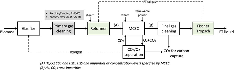
FIGURE 2. Schematic of the process configuration evaluated in this work.
2.1 Molten Carbonate Electrolysis Cell
Experimental investigations have shown that high-temperature electrolysis of MCEC (Hu et al., 2016a; Hu et al., 2017) benefits from both thermodynamic and kinetic properties of the electrochemical process resulting in an improved overall conversion efficiency. High temperature also reduces the electricity required to drive the electrolysis process because part of the reaction energy is supplied in the form of heat. Besides, MCEC often use molten alkali metal carbonate salts as electrolyte, requiring operational temperatures in the range 600–800°C.
The working principle of MCEC is shown in Figure 3. In the electrochemical reactions that take place in the cell, electrical power is converted into energy-rich gas, or in case of the reverse operation as a molten carbonate fuel cell (MCFC), producing electrical power. Hydrogen is produced on the cathode side through the electrochemical reaction of water, carbon dioxide and 2 electrons forming hydrogen and a carbonate ion. The carbonate ions migrate in the electrolyte from one electrode to the other, where they are decomposed to oxygen and carbon dioxide, facilitating a separation of the carbon dioxide from the product gas. After separation the carbon dioxide is either recycled to the MCEC cathode or separated for sequestration. Oxygen can be utilized in the thermal gasification. In the output stream from the cathode, the CO content can be controlled through the water-gas shift reaction and thus enabling a control of the H2/CO ratio.
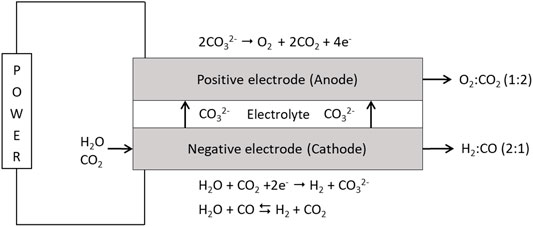
FIGURE 3. MCEC operating principle (Hu, 2016).
The high operating temperature of the MCEC can potentially enable internal reforming of methane and other hydrocarbons, especially if Ni is used as electrode (cathode), which can also improve the overall efficiency of the system. Information about acceptable concentration levels of hydrocarbons is not available, but values for MCFC are probably reasonable approximations. These limits are saturated hydrocarbons including methane <10% vol., aromatic and cyclic hydrocarbons <0.5%vol. (Dayton et al., 2001), H2S <5ppmv (Remick 1986; Dayton et al., 2001), NH3 <0.01%vol., and HCl <0.1ppmv (Srinivasan 2006).
The behavior of the MCEC has been simulated with a numerical model developed in MATLAB/Simulink. The model of the MCEC stack used in the study is a zero-dimensional model in which molar and energy balances, chemical reactions (steam reforming and water gas shift) and electrochemical reactions (with the related aspects on current and voltage) are taken into account.
The MCEC stack model is part of a Simulink model developed in this work, Figure 4. The input to the cathode (fuel electrode) consists of the mix among three streams: a syngas with given composition, a fixed amount of steam (usually given in proportion to the water vapor content of the syngas) and the recycled carbon dioxide from the anode (oxygen electrode) outlet. The input current to the MCEC stack is determined by a control system so that the proportion between the molar flows of hydrogen and carbon monoxide at cathode outlet is equal to 2.
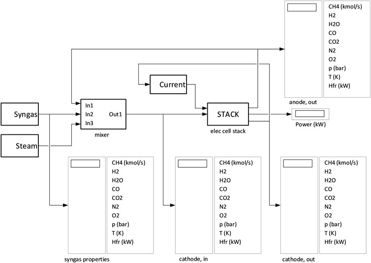
FIGURE 4. MCEC Simulink model.
The inputs to the MCEC stack model are:
- Molar flow rates of the components of the gas at the inlet of the fuel cathode (the seven chemical species involved in the model are: CH4, H2, H2O, CO, CO2, N2, and O2).
1) Pressure and temperature of the gas at the inlet of the cathode (the cell stack is assumed to operate at atmospheric pressure)
2) Input electric current to the cell stack
Parameters of the stack are the number of cells and cell size, which are needed to calculate current density. The outputs of the MCEC stack model are:
1) Molar flow rates of the components of the gas at the outlet of the cathode
2) Molar flow rates of the components of the gas at the outlet of the anode
3) Cell stack temperature (which is also the temperature of the gases at the outlet of the electrodes)
4) The electric power required by the cell stack
The calculation of the outputs requires the convergence of an iterative procedure, since all output quantities are heavily interdependent and cannot be determined separately from the knowledge of the inputs only. Details on the equations considered in this iterative procedure are given in the Supplementary Material.
2.2 Gasification
There are several gasification technologies that can utilize sawmill byproducts. Given the nature of the feedstock, technology knowledge and specific site constraints, we opted to explore 1) the WoodRoll process; 2) indirectly heated dual fluidized bed; 3) directly heated fluidized bed. All the gasification processes are scaled to produce 20 MW of product gas (LHV basis). A brief description of these technologies is presented in the following subsections.
2.2.1 WoodRoll Process
WoodRoll (WR) technology, developed by Cortus Energy AB, converts biomass to a clean renewable gas mainly composed of CO and H2. The WR process produces relatively high-quality syngas with moderate need for gas cleaning, compared to fluidized bed configurations, before its utilization to produce liquid fuels for transportation and industrial purposes. The WR process includes multiple process stages, the major steps being feedstock drying, pyrolysis and gasification. The pyrolysis process generates char and gas. The char is gasified in an indirectly heated entrained flow gasifier, using steam in a subsequent step. The pyrolysis gas is combusted to sequentially supply the heat required in the gasification reactor (1,100°C), the pyrolysis process (400°C) and the drier (100°C), as illustrated in Figure 5 (Phounglamcheik et al., 2017). Cortus energy AB has installed a 6 MW WoodRoll process demonstration plant at a metal powder production facility in Höganäs, Sweden. The purpose was to provide Höganäs AB metal powder production process with green energy syngas derived from the WoodRoll plant. A pilot scale, 500 kW, WoodRoll process was previously demonstrated in Köping, Sweden (Amovic et al., 2014).
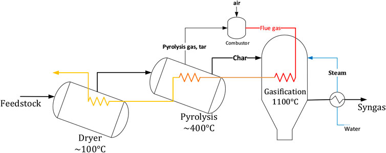
FIGURE 5. Schematic of the WoodRoll gasification process developed by Cortus Energy AB (Phounglamcheik et al., 2017).
2.2.2 Indirectly Heated Dual Fluidized Bed
Dual Fluidized Bed (DFB), the most widely used configuration for indirect gasification of biomass, essentially employs two fluidized bed reactors (one for gasification and one for combustion) linked by the bed material, circulating between them (Figure 6A). Different fluidization media can be used in the two reactors. A widely accepted configuration is to use steam and air in the gasification and the combustion reactor, respectively (Motta et al., 2018). The gasification reactor is often a bubbling fluidized bed (BFB) and the combustor a circulating fluidized bed (CFB), as CFB boilers can utilize a wide range of feedstocks both in terms of moisture content and size. In a DFB configuration biomass is supplied to the gasification reactor and part of the produced char is combusted in the combustor to preheat the bed material prior to its re-entry to the gasifier. The capacity of the combustor can be scaled separately to boost steam generation by directly supplying additional biomass. GoBiGas plant in Sweden has demonstrated 20 MW biomethane production from 32 MW feedstock using DFB configuration (Thunman et al., 2018), including lessons learned for scalability (Thunman et al., 2019).
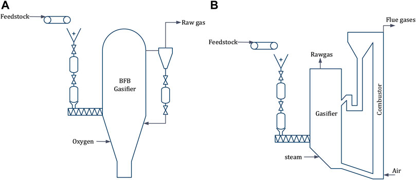
FIGURE 6. Fluidized bed reactor configurations, dual fluidized bed (A) & bubbling fluidized bed (B).
2.2.3 Directly Heated Bubbling Fluidized Bed
An oxygen-blown fluidized bed gasification technology was considered as relevant given the fact that the MCEC produces an oxygen rich stream as byproduct (Figure 6B). To this end, the bubbling fluidized bed (BFB) configuration developed by Andritz Carbona is an interesting option to consider, because it is a well-established technique with a commercial installation in Skive, Denmark (Motta et al., 2018; Salo and Horvath, 2009) and a demonstration plant at GTI in Chicago, United States (Motta et al., 2018).
2.3 Fischer Tropsch Synthesis
The FT process is a proven technology for converting synthetic gas to liquid crude and can help unlock the potential of forest feedstock to replace fossil use in the transport sector. FT synthesis (FTS) is essentially an exothermic process operated at temperature in the range of 200–350°C and pressure in the range of 10–65 bar (Guettel et al., 2008). The major chemical reactions in the FTS are summarized in (Laan and Beenackers 1999). The formation of the desired products, alkanes and alkenes, are exothermic reactions and produce water. The water gas shift reaction (WGS) also takes place over most metal catalysts balancing the CO and H2 ratio. Side reactions such as those producing alcohols and carbon deposits via Boudouard reaction, as well as oxidation and reduction of the catalysts may occur in the FTS reactor. The conversion process is often catalyzed by metals such as cobalt, iron and ruthenium. In this project the FT process was operated at 240°C and 20 bar. The operational temperature is controlled with a continuous supply of cooling water. The FT products follow Anderson-Schulz-Flory (ASF) model with alpha parameter set at 0.9 and CO conversion 85%.
2.4 Gas Conditioning
For optimal conversion, the syngas composition prior to the FT reactor must satisfy the following criteria:
1) H2 to CO molar ratio 2
2) Inert components such as nitrogen and H2S should be below the tolerance limit specified by technology developers
As presented in Table 1, the syngas after primary cleaning contain H2 to CO ratios 2.04, 1.71, and 0.72 for the WR, BFB and DFB, respectively. At this stage, depending on the gasification technology, the syngas also contains tar, hydrocarbons such as methane, C2Hx and benzene that reduce the overall carbon conversion from biomass to finished products when left unutilized. It would be wise to reform the methane and light hydrocarbons to CO and H2 components.
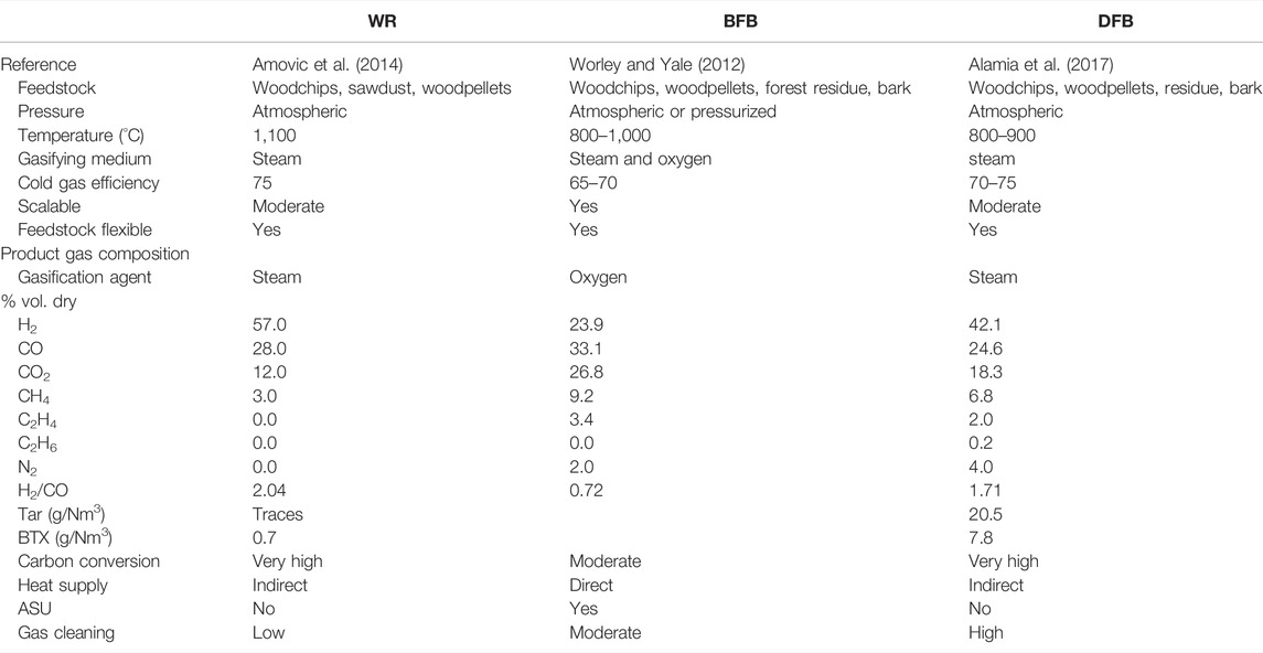
TABLE 1. Gasification technologies.
There are several gas reforming technologies commercially available, such as steam reforming (SMR) and partial oxidation (POX). SMR can be further classified depending on the source of the thermal energy required to drive the process, e.g., by partially combusting the incoming gas in an integrated furnace (Baltrusaitis and Luyben 2015) or by using electrically (resistance) heated reactor surfaces (Wismann et al., 2019). Compared to the conventional side fired SMR, the resistance heated is expected to achieve remarkable reduction in reformer volume as the furnace and its accessories become unnecessary (Wismann et al., 2019). The resistance heated reformer is yet to be proven at commercial scale.
It was not straight forward which technology and process configuration would lead to the best yield and economic performance. A total of six cases were evaluated, two process configurations for each gasification technology. The configurations differ mainly on the downstream handling of light hydrocarbons (C1–C6) and tar in the raw gas. In summary, the following configurations were investigated:
1) Side-fired steam reformer (SMR)
2) electric heated steam reformer (eSMR)
2.4.1 Side-fired Steam Reformer
In the SMR configuration, light hydrocarbons (C1–C6) in the raw gas, FT tail gas and off-gases from upgrading were reformed to CO and H2 using side-fired SMR unit. In this part of the FT configuration, tail gas must be combusted to supply the heat required to drive the SMR and the remainder of the FT tail gas was mixed with the fresh raw gas entering the SMR.
Distinctive features are:
1) Cooling of cathode stream generate saturated steam at 35 bar
2) Cooling of anode stream produce saturated steam at 5 bar for internal use in the MCEC and the steam reformer
3) SMR combustor exhaust gases sent to the integrated CHP system to supplement production of high-pressure steam
4) Process steam deficit is assumed to be supplied from the CHP system
2.4.2 Electric Heated Steam Reformer
In the eSMR configuration, light hydrocarbons in the raw gas, FT tail gas and off gases from upgrading were reformed to CO and H2 using electric resistance heated reactor surfaces. A small fraction of the FT tail gas must be purged to limit accumulation of inert compounds in the FT reactor feed.
Distinctive features are:
1) Cooling of cathode stream generate saturated steam at 35 bar
2) Cooling of anode stream produce saturated steam at 5 bar for internal use in the MCEC and the steam reformer
3) Purge adjusted to limit accumulation of inert components in the stream entering the FT reactor
4) Purge stream used as fuel in the CHP system
5) Process steam deficit is assumed to be supplied from the CHP system
2.5 Improved Cryogenic Separation Process
The molar composition of the stream exiting the anode side of the MCEC is two-thirds CO2 and one-third O2. With such high concentration of CO2, the anodic stream is suitable for linking to carbon capture techniques. The benefit is twofold, reducing the carbon footprint of the overall process and to deriving income from the separated pure O2 stream. An improved cryogenic separation process (Xu et al., 2014) with multiple refrigeration and condensation steps was developed and applied to the anodic stream achieving molar purity of 99.9% CO2 in a final distillation step. Depending on the process configuration and gasification process, 20–50% of the separated CO2 is recycled back to the MCEC feed and the rest is assumed to be sequestered.
2.6 Compressor
The gasification technologies considered, the associated primary gas cleaning units and the MCEC are operated at atmospheric pressure, whereas the FT reactor benefit from high operational pressure both in terms of favorable reaction kinetics and reduced equipment size. Thus, the syngas after the MCEC is compressed to 22 bar using a two stage compressor with inter- and aftercooling.
2.7 Acid Gas Removal
Depending on the gasification technology the syngas initially contains 12%–27% vol. CO2. Though the MCEC utilizes CO2 to form the carbonate ion conductor through the electrolyte, part of the incoming CO2 inevitably follows the cathodic stream that proceed to the FT island. CO2 is not needed in the FT synthesis and must be removed to minimize reactor size and thereby cost. Besides, poisonous gases that are harmful to the FT catalysts such as H2S and ammonia may also be present in the syngas. Therefore, CO2 and other impurities must be kept below limits specified by FT technology developers. Amine-wash technology was implemented to ensure these impurities remain below the specs. Zinc guard bed ensures sulfur content is limited to a few ppm H2S.
3 Methodology
3.1 Process Modelling
Literature data was used for the gasification technologies evaluated. The conversion of synthesis gas to FT products was carried out based on the model developed in this work. The MCEC model was built in MATLAB Simulink environment based on experimental polarization data (Hu et al., 2014; Hu, Lindbergh, and Lagergren 2016b). The MCEC model was soft linked to the rest of the process steps which were developed in UniSim Design. Yield and energy performance of the FT process was derived from published experimental data (Hanaoka et al., 2015; Snehesh et al., 2017) and implemented in UniSim Design as a yield reactor.
3.2 Process Integration
The MCEC unit was integrated at a sawmill site. At a typical Nordic sawmill, significant part of the incoming timber ends up in byproduct category in the form of bark, woodchips and sawdust. Under business as usual operation, about 10.3% wt. dry basis of the byproducts is combusted onsite to preheat drying air that circulates through a drying kiln where the fresh sawn wood (lumber) is stored (Anderson and Toffolo 2013). The rest of the byproducts are exported to other process industries such as pulp mills and wood pellet plants.
In the current framework, the byproducts are utilized to produce SAF where the heat demand of the drying kiln is satisfied using heat derived from the SAF plant. In case the SAF plant does not produce enough heat to satisfy the drying kiln, part of the byproducts will be combusted in the integrated boiler of the steam system. The gasification technologies considered in this study were scaled to produce 20 MW syngas (LHV basis). The feedstock required to achieve the target syngas energy was used to indicate sawmill size and derive the corresponding drying kiln thermal energy load. The sawmill was sized to match feedstock requirements of the gasification unit and the biomass boiler. The boiler was run to satisfy any heat deficit in the integrated system and to superheat saturated steam derived from the SAF facility at medium and intermediate pressure levels.
There are high temperature processes in the SAF island, e.g., SMR exhaust, conditioned syngas cooling, and low temperature heat demand in the sawmill, e.g., preheating of drying air, local room heating. To exploit the thermal energy of high temperature process streams and minimize exergy destruction, a common steam system can be suitably designed taking advantage of the temperature difference between the heat sources and sinks. Besides, steam is required in the SAF facility to drive the SMR and MCEC. Integrated design approach was implemented as illustrated in Figure 7. Pinch Analysis was applied to ensure heat transfer feasibility among the hot and cold process thermal streams thereby minimizing external utility requirements.
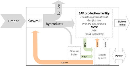
FIGURE 7. System boundaries of the integrated SAF production at the sawmill facility.
3.3 Economic Assumptions
Production cost of total FT liquid and aviation fuel were evaluated as an economic indicator of the cases evaluated. The total fixed capital investment (TFCI) of the process configurations were evaluated by accounting the equipment cost of major process units and applying factors to account for direct cost (equipment erection, piping, instrumentation and control, electricals, utilities, off-site, buildings) and indirect cost (design, engineering and construction, contingency) (Smith 2005). Investment cost of most of the major process units are based on published data and the sources are outlined in the Supplementary Material. All investment costs are scaled to fit equipment sizes required in this work and were adjusted for inflation to the reference year 2017. Monetary value conversion factors 0.1 and 0.85 are used for SEK to Euro and USD to Euro, respectively. Annuity method is applied to annualize the TFCI assuming 8% interest rate and 20 years economic lifetime, resulting in a capital recovery factor of 0.1. Annual O&M was fixed at 3% of TFCI (includes costs for operating supplies, planned and unplanned maintenance and repair, spare parts and payroll). The prices of energy carriers (feedstock, electricity, and co-products) and other materials (oxygen, scrubbing media) that constitute to the variable operating cost are presented in Table 2. A plant availability of 7884 h (corresponding to 90% availability) was assumed.
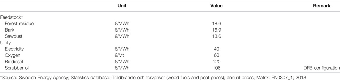
TABLE 2. Economic parameters.
3.4 GHG Performance Evaluation
GHG performance of the cases were evaluated using a simplified approach based on the revised Renewable Energy Directives (RED II) guidelines. Accordingly, the allocations are made based on energy of products which stops where the product streams are distributed. In this study, the main product is FTL which fractionates into SAF and other hydrocarbons (diesel and naphtha ranges) components in the final stage. Emissions deriving from procurement of timber, processing of timber to lumber (electricity use) and export of lumber are not impacted by the utilization of sawmill byproducts, hence are excluded from the GHG performance evaluation. The integrated processes produce two CO2 concentrated streams, MCEC anode and AGR, which are suitable for carbon capture and storage (CCS). Thus, two GHG performance indicators are evaluated, with and without a CCS option. The following emission factors are assumed: Swedish electricity mix 13.1 gCO2eq/MJ (Energimyndigheten, 2020), transport of FTL 1.55 kgCO2eq/MWh, and transport of CO2 by truck (0.108 kgCO2eq/ton-km) and ship (0.03 kgCO2eq/ton-km) [Innovation Fund (InnovFund). 2021] for CCS cases.
4 Results
4.1 MCEC Performance
MCEC performance significantly depends on the incoming syngas composition and the downstream upgrading technique. In fact, the electrochemical unit consumes electrical energy and steam to boost the H2 content of the incoming syngas to meet a target H2 to CO ratio that is optimal for the downstream upgrading technique. MCEC contribution is in general magnified when supplied with particle and tar free product gas lean in hydrogen content. In molten carbonate units CO2 must be present in the cell to transfer O2 in the form of
The syngas stream at the cathode exit is primarily composed of H2 and CO readily upgradable to liquid hydrocarbons in an FT unit, combined represent more than 88% vol. dry basis with H2 to CO molar ratio 2:1. Depending on the composition of the syngas feed to the MCEC, methane, CO2 and N2 may also be present in the cathode exit stream. The anode exit is a mixture of CO2 and O2 in the ratio 2:1, respectively. This stream undergoes a cryogenic separation process and part of the separated CO2 is recycled back to the feed of the MCEC. The amount of CO2 that can be recycled is directly proportional to the MCEC activity.
The molar ratio of H2 to CO in the syngas derived from the WR and DFB gasification processes are not far from 2, which is the optimal ratio for FT upgrading technique, hence the MCEC exhibited a limited activity for these cases. The syngas from the BFB has however a very lean hydrogen content, which required increased MCEC activity to meet the optimal syngas quality for the FT process. Through the application of the MCEC, the energy content of syngas is magnified with factors 1.26, 1.30, and 1.4 for the WR, DFB, and BFB cases, respectively. It should be noted that these figures correspond to the operating parameters of the MCEC, amount of steam feed and amount of CO2 recycle chosen for each configuration. The methane content in the conditioned syngas marginally contributes to its total energy content, about 6% on a LHV basis.
In the BFB case, in which the activity of the MCEC was the highest, it is not straightforward to pick an optimal operating condition for the MCEC. Figure 8 shows the performance of the MCEC for the BFB technology under CO2 recycle 0%–50% and current density 0–0.1 A/cm2. High current density leads to low methane fractions at cathode exit (Figure 8A) high stack temperature (Figure 8B) Band high power consumption. An energy efficiency indicator, that compares energy content of syngas before and after the MCEC, was introduced to measure performance of the MCEC in boosting the syngas energy. When biofuel production is the priority, the MCEC should be operated at high current density under high CO2 recycling in order to maximize the yield of the conditioned syngas and disfavor the formation of methane as a result of the associated high stack temperature, Figure 8B. However, this configuration does not necessarily lead to the best energy efficiency, especially when the electricity that drive the MCEC is included in the equation. Both scenarios are therefore evaluated, one maximizing the yield of conditioned syngas and the other leading to an optimal energy efficiency.
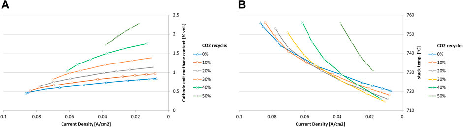
FIGURE 8. BFB case MCEC performance, methane content at cathode exit (A) and stack temperature (B).
4.2 Overall Process Performance
Table 3 presents a summary of mass and energy flows for total FT liquids and SAF production of relevance for the techno-economic and greenhouse gas emission assessment. The investigated cases resulted in annual total hydrocarbon production of 9–12 kT, depending on the process configuration and gasification technique. Mass and energy balances of major streams can be found in Supplementary Material. The conversion efficiency (LHV basis) from biomass to renewable hydrocarbon components was estimated to 49%–58% and 57%–61% for SMR and eSMR configurations, respectively. It should be noted that the conversion efficiencies refer to the additional biomass, i.e., the difference between the internal consumption for a standalone operation of the sawmill and the integrated cases. On energy basis, the eSMR configurations improved the yield by about 9%–13% compared to their SMR counterparts.

TABLE 3. Summary of inputs and biofuel production.
Product selectivity, which leads to the yield of SAF, is strongly dependent on the FTS process configuration and catalyst. Upgrading of FT crude yields different fractions of hydrocarbon products, naphtha-, aviation-, and diesel-ranges. The results presented in Table 3 assume a 60% wt. conversion FTP to SAF and the rest are grouped as other hydrocarbons (OHC).
The integrated process design approach showed that a significant part of the lumber drying process can be covered using steam generated from the high temperature process streams of the SAF plant. This is evident from Figure 9 (generation) where the production of high-pressure steam (HPS) from the biomass boiler is minor, about 1%–25% of the total steam generation. Saturated steam at 35 bar (IPS) and 12 bar (MPS) are derived from cooling of conditioned syngas exiting the MCEC cathode and FT reactor, respectively. Both streams are superheated in the biomass boiler to allow mixing with expanding HPS at their respective pressure levels, thereby maximizing electricity production of the integrated process. The SAF facility both generates and consumes saturated steam at 5 bar (LPS). LPS is produced from cooling of the stream exiting the MCEC anode and consumed by the SMR and MCEC. The SAF facility has net deficit in LPS. Therefore, the LPS exiting the back-pressure turbine of the steam system is split between SAF plant and the sawmill drying process (Figure 9, consumption). The sawmill consumes LP steam (SMLPS) to preheat the drying air entering the drying kiln.
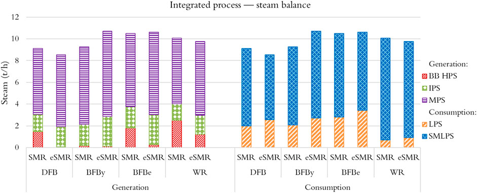
FIGURE 9. Steam balances for all integrated process configurations.
4.3 Economic Performance
Estimated specific capital investment per unit MW of FTP, and categorized by process section, are shown in Figure 10. For the WR cases, the gasification train (which includes a dryer and a pyrolysis reactor) is the largest contributor, about 30%, followed by the gas conditioning category (which includes the MCEC unit), about 25%. The order shifts for the DFB and BFB configurations in which the gas conditioning category becomes the largest contributor, 26% DFB and 30%–35% BFB. For the BFB cases, this shift derives from the MCEC unit which resulted in capital expenditure about 1.5 and 2.5 times larger than that of the WR and DFB cases for BFBe and BFBy configurations, respectively. In general, the processes evaluated are predictably capital intensive due to the relatively small production scales, the technological maturity of the MCEC and limited integrability with the host facility.
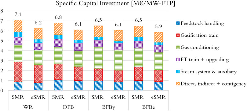
FIGURE 10. Comparison of specific capital investment per MW-FTP.
FTL production cost breakdowns for the configurations evaluated are shown in Figure 11. Accordingly, all cases resulted in production cost range 140–155 €/MWh-FTP. The eSMR cases correspond to the lower end of the range, 140–146 €/MWh-FTP. Clearly, using electric resistance heated reformer has improved the yield which in turn reduced the production cost. On average, about 55% of the production cost derives from the total fixed capital investment (TFCI), about 20% feedstock procurement, and about 16% operation and maintenance.
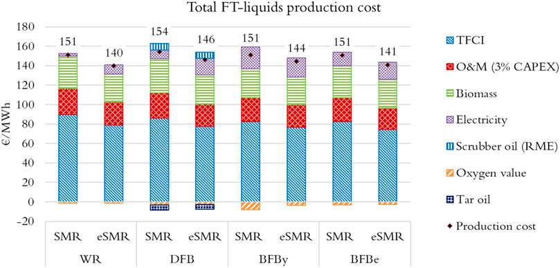
FIGURE 11. Comparison of FTL production cost breakdown.
To shed light on the SAF production potential, the FTL production costs were compared to jet biofuel prices reported in the inquiry for Swedish jet biofuel blending mandate (Wetterstrand et al., 2019). The inquiry investigated SAF blending obligation in the Swedish aviation industry up to 2030 in which the contribution of jet biofuel was projected to increase from about 1% vol. in 2021 to 30% vol. in 2030. Jet biofuel prices 185 and 124 €/MWh were estimated for 2021 and 2030, respectively (the latter is recalculated assuming a jet fuel calorific value of 35 MJ/L). It should be noted that this comparison is only indicative since the assumptions behind the evaluations are not necessarily the same.
4.4 GHG Performance
The GHG performance of the cases were evaluated with and without a CCS option and the results are shown in Figure 12. The SAF and hydrocarbons (diesel and naphtha range) produced will be used to replace fossil counter parts. Thus, the GHG performance of the cases were compared to a GHG performance of a fossil reference system evaluated by allocating emissions according to the energy share of SAF, petrol and diesel in the product using fossil emission factors 87 gCO2/MJjetfuel (Tzanetis et al., 2017), 93 gCO2/MJpetrol and 95 gCO2/MJdiesel (Jafri et al., 2020). The CCS options consider 85% efficiency on the CO2 capture technology, commercial technology based on amine solvent (Güleç et al., 2020), and the captured CO2 is transported to long-term storage sites by truck and ship assuming 200 and 1,200 km of land and maritime distances, respectively. GHG emissions saving potential of 87%–97% for the cases without CCS option and 120%–150% for those with CCS option can be realized. The carbon footprint of product distribution (0.43 gCO2/MJbiofuel) and CO2 transport (1.18–3.42 gCO2/MJbiofuel) to the net GHG emissions are significantly smaller than that of electricity (1.81–15.01 gCO2/MJbiofuel). The cases were able to satisfy the 65% GHG reduction for new plants set by RED II, thanks to the low carbon footprint of the expanded system feedstocks, biomass and electricity.
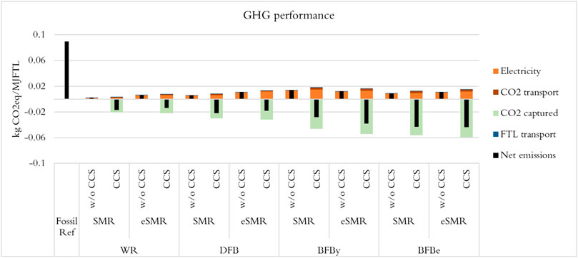
FIGURE 12. Comparison of GHG performance.
5 Discussion
Given the fact that methane was present at the cathode under all scenarios, though at varying degree, a reformer is inevitable when the target product is other than methane. In this regard, the MCEC effectively replaces the water gas shift (WGS) process of the conventional gasification-based biofuels value chains evaluated. To indicate on the benefits of the MCEC, reference configurations were evaluated based on process flow diagrams that included a WGS and a SMR. These reference cases resulted in 7.86, 8.39, and 8.77 kTPY of FTP production for the WR, DFB and BFB cases, respectively. Compared to the MCEC results, Table 3, the increment in FTL productivity were 5%–19% (SMR) and 15%–31% (eSMR), depending on the syngas quality (gasification technology) and reformer configuration. Thus, the benefit of the MCEC over WGS is twofold: the MCEC improves the yield by improving the carbon conversion efficiency and creates a link for the direct utilization of external CO2 in the context of power-to-X. It is noteworthy that the MCEC is the attractive option even without considering the latter benefit.
It is evident that electrification of the SMR showed significant impact on the yield. This outcome sheds light on the importance of carbon tracking in the conversion processes (the carbon balances for all the investigated cases are presented in Supplementary Material). This study was limited to analyze the MCEC considering only the carbon content of the syngas, in the form of CxHy, CO and CO2. Consequently, the performance of the MCEC was constrained to meet the cathode exit syngas quality that was set as a target. Certain amount of the CO2 exiting the anodic side was recycled to the feed of the MCEC to increase the overall carbon efficiency. Under such configuration, the maximum attainable carbon conversion efficiency is set by the carbon content of the incoming syngas.
Depending on the gasification technology, about 63% wt (WR), 68% wt (DFB) and 88% wt (BFB) of the carbon in biomass ends up in the syngas. Thus, in order to enhance the performance of the MCEC to increase carbon conversion, as much as possible of biomass carbon must be kept in the syngas. In this regard, finding alternative ways to supply the thermal heat required to drive the gasification process can bring the carbon conversion to syngas close to 100%. These aspect of the MCEC performance are best clarified by the BFB cases, in which the highest MCEC activity was observed. The MCEC adds flexibility to the process, for instance by adjusting the operating condition of the MCEC. The amount of carbon at the anode can be controlled to reduce the load on the AGR.
It should be noted that the contribution of electricity to biofuels in the context of the configurations evaluated in this study was not limited only to the MCEC, but also to the reformer (eSMR scenarios) and the cryogenic separator that purifies CO2. The anode exhaust is rich in CO2 concentration (67% vol.), the remainder being oxygen. This stream undergoes cryogenic separation to produce 99.9% vol. CO2 and oxygen-rich fractions. A part of the CO2 separated (20%–50%) was recycled to the feed stream of the MCEC to facilitate the operation of the MCEC primarily serving as carbonate ion source, and part of it is captured.
Electrochemical reduction of CO2 to CO and C in MCEC has been studied (Kaplan et al., 2010; Ren et al., 2015; Küngas 2020). A recent experimental study of MCEC (Meskine et al., 2020) has confirmed that electrochemical reduction of CO2 to CO was observed at the cathode in the presence of steam. Considering such reports, co-electrolysis (electrolysis of steam and CO2) operation mode of the MCEC is something that needs close investigation. This is particularly relevant due to its potential interplay with methane formation mechanism, assuming the most relevant gaseous products of CO2 electrolysis are CO and CH4 (Meskine et al., 2020).
One of the main drawbacks of carbonate cells is of course their low carbon conversion efficiency due to the continuous formation of CO3= at the cathode that gets protonated at the anode to release CO2. For every reduction of H2O to H2, one CO2 is released at the anode. MCEC are often operated under excess CO2 supply to support high current densities required to maintain a steady stack temperature.
The results presented and discussed here refer to the situation in Sweden. However, the results are expected to remain proportional in other locations assuming the same cost of technology applies. The variables that may affect the assessment most are the availability and cost of biomass (and byproducts) and renewable electricity or carbon intensity of the national electricity mix.
6 Conclusion
This study has established operating conditions of MCEC for syngas conditioning applications. Under low current density mode, the MCEC favors the formation of methane. Under high current density mode, the MCEC disfavors formation of methane but the power consumption is high. For all the cases evaluated, methane was present at the cathodic exit which may or may not be attractive depending on the final product. For FT applications, a methane reformer is inevitable to achieve acceptable yields. The activity of the MCEC varied when supplied with the different synthesis gases derived from the WR, DFB, and BFB gasification techniques. The BFB technology generates syngas with the least hydrogen content and promoted highest activity in the MCEC. Both the DFB and WR technologies generate syngas quality that are not far from the optimal for FTS and, hence, the MCEC activity for these cases was low.
Electrification of the steam reforming (eSMR) improved the overall yield of FTP by 9%–13% compared to the SMR cases and by 15%–31% compared to the conventional configurations with WGS. This indicates that there is room for fine tuning gasification-based processes to increase carbon conversion efficiency.
Under the assumed economic conditions, biofuels can be produced at a cost of 140–155 €/MWh-FTP, the lower end of the range corresponding for eSMR configurations. Clearly, using electric resistance heated reformer has improved the yield by as much as 13%, which in turn reduced the production cost.
Data Availability Statement
The datasets presented in this study can be found in online repositories. The names of the repository/repositories and accession number(s) can be found in the article/Supplementary Material.
Author Contributions
SM and AT designed the framework, performed the analysis, and contributed to writing and implementation of the work. KE contributed with MCEC input data, state-of-the-art of the MCEC, writing and edition.
Funding
This work was carried out within the collaborative research program Renewable transportation fuels and systems (Förnybara drivmedel och system), Project No. 48371–1. The project has been financed by the Swedish Energy Agency and f3—Swedish Knowledge Centre for Renewable Transportation Fuels, and co-financed by Bio4Energy (a Strategic Research Environment appointed by the Swedish government).
Conflict of Interest
The authors declare that the research was conducted in the absence of any commercial or financial relationships that could be construed as a potential conflict of interest.
Publisher’s Note
All claims expressed in this article are solely those of the authors and do not necessarily represent those of their affiliated organizations, or those of the publisher, the editors and the reviewers. Any product that may be evaluated in this article, or claim that may be made by its manufacturer, is not guaranteed or endorsed by the publisher.
Acknowledgments
We acknowledge the in-kind contribution of Cortus Energy AB.
Supplementary Material
The Supplementary Material for this article can be found online at: https://www.frontiersin.org/articles/10.3389/fenrg.2022.799553/full#supplementary-material
References
Ail, S. S., and Dasappa, S. (2016). Biomass to Liquid Transportation Fuel via Fischer Tropsch Synthesis - Technology Review and Current Scenario. Renew. Sustain. Energy Rev. 58 (May), 267–286. doi:10.1016/j.rser.2015.12.143
Alamia, A., Larsson, A., Breitholtz, C., and Thunman, H. (2017). Performance of Large-Scale Biomass Gasifiers in a Biorefinery, a State-Of-The-Art Reference. Int. J. Energy Res. 41 (14), 2001–2019. doi:10.1002/er.3758
Amovic, M., Donaj, P., Moner, B., Alzuheri, R., and Ljunggren, R. (2014). Fuel testing procedure for pyrolysis and gasification of biomass using TGA and WoodRoll test plant. Malmö, Sweden: Svenskt Gastekniskt Center AB. Available at: http://www.sgc.se/ckfinder/userfiles/files/SGC293.pdf.
Anderson, J.-O., and Toffolo, A. (2013). Improving Energy Efficiency of Sawmill Industrial Sites by Integration with Pellet and CHP Plants. Appl. Energy 111 (November), 791–800. doi:10.1016/j.apenergy.2013.05.066
Baliban, R. C., Elia, J. A., Floudas, C. A., Gurau, B., Weingarten, M. B., and Klotz, S. D. (2013). Hardwood Biomass to Gasoline, Diesel, and Jet Fuel: 1. Process Synthesis and Global Optimization of a Thermochemical Refinery. Energy fuels. 27, 4302–4324. doi:10.1021/ef302003f
Baltrusaitis, J., and Luyben, W. L. (2015). Methane Conversion to Syngas for Gas-to-Liquids (GTL): Is Sustainable CO2 Reuse via Dry Methane Reforming (DMR) Cost Competitive with SMR and ATR Processes? ACS Sustain. Chem. Eng. 3 (9), 2100–2111. doi:10.1021/acssuschemeng.5b00368
Barckholtz, T. A., Elsen, H., Kalamaras, P. H., Kiss, G., Rosen, J., Bove, D., et al. (2021). Experimental and Modeling Investigation of CO3=/OH- Equilibrium Effects on Molten Carbonate Fuel Cell Performance in Carbon Capture Applications. Front. Energy Res. 9 (June), 1–15. doi:10.3389/fenrg.2021.669761
Bove, R., Moreno, A., and Mcphail, S. (2008). International Status of Molten Carbonate Fuel Cell (MCFC) Technology Output Voltage Internal Resistance. Luxembourg: JRC Scientific and Technical Reports. Available at: http://publications.jrc.ec.europa.eu/repository/bitstream/JRC44203/mcfc_status.pdf.
Chen, B., Xu, H., and Ni, M. (2017). Modelling of SOEC-FT Reactor: Pressure Effects on Methanation Process. Appl. Energy 185 (January), 814–824. doi:10.1016/j.apenergy.2016.10.095
Chen, L., Chen, F., and Xia, C. (2014). Direct Synthesis of Methane from CO2-H2O Co-electrolysis in Tubular Solid Oxide Electrolysis Cells. Energy Environ. Sci. 7 (12), 4018–4022. doi:10.1039/C4EE02786H
Chery, D., Lair, V., and Cassir, M. (2015). CO2 Electrochemical Reduction into CO or C in Molten Carbonates: A Thermodynamic Point of View. Electrochimica Acta 160, 74–81. doi:10.1016/j.electacta.2015.01.216
Clausen, L. R., Houbak, N., and Elmegaard, B. (2010). Technoeconomic Analysis of a Methanol Plant Based on Gasification of Biomass and Electrolysis of Water. Energy 35 (5), 2338–2347. doi:10.1016/j.energy.2010.02.034
Dayton, D. C., Ratcliff, M., and Bain, R. (2001). Fuel Cell Integraton - A Study of the Impacts of Gas Quality and Impurities. Milestone Report. USA: National Renewable Energy Laboratory.
Di Giulio, N., Bosio, B., Cigolotti, V., and Nam, S. W. (2012). Experimental and Theoretical Analysis of H2S Effects on MCFCs. Int. J. Hydrogen Energy 37 (24), 19329–19336. doi:10.1016/j.ijhydene.2012.03.086
Energimyndigheten (2020). Drivmedel 2019-Redovisning av Rapporterade Uppgifter Enligt Drivmedelslagen, Hållbarhetslagen Cch Reduktionsplikten. Eskilstuna, Sweden: Swedish Energy Agency. Available at: https://www.energimyndigheten.se/globalassets/nyheter/2020/er-2020_26-drivmedel-2019.pdf.
Eurostat, (2018a). Pulp, Paper and Paperboard. Available at: https://ec.europa.eu/eurostat/data/database (Accessed November 30, 2021).
Eurostat, (2018b). Total Sawnwood Production. Available at: https://ec.europa.eu/eurostat/data/database (Accessed November 30, 2021).
Ferguson, S., and Tarrant, A. (2021). Molten Carbonate Fuel Cells for 90% Post Combustion CO2 Capture from a New Build CCGT. Front. Energy Res. 9 (July), 1–6. doi:10.3389/fenrg.2021.668431
Giglio, E., Lanzini, A., Santarelli, M., and Leone, P. (2015). Synthetic Natural Gas via Integrated High-Temperature Electrolysis and Methanation: Part I-Energy Performance. J. Energy Storage 1, 22–37. doi:10.1016/j.est.2015.04.002
Guan, G., Kaewpanha, M., Hao, X., and Abudula, A. (2016). Catalytic Steam Reforming of Biomass Tar: Prospects and Challenges. Renew. Sustain. Energy Rev. 58, 450–461. doi:10.1016/j.rser.2015.12.316
Güleç, F., Meredith, W., and Snape, C. E. (2020). Progress in the CO2 Capture Technologies for Fluid Catalytic Cracking (FCC) Units-A Review. Front. Energy Res. 8 (April), 1–14. doi:10.3389/fenrg.2020.00062
Hanaoka, T., Miyazawa, T., Shimura, K., and Hirata, S. (2015). Jet Fuel Synthesis from Fischer-Tropsch Product under Mild Hydrocracking Conditions Using Pt-Loaded Catalysts. Chem. Eng. J. 263 (March), 178–185. doi:10.1016/j.cej.2014.11.042
Hillestad, M., Ostadi, M., Alamo Serrano, G. d., Rytter, E., Austbø, B., Pharoah, J. G., et al. (2018). Improving Carbon Efficiency and Profitability of the Biomass to Liquid Process with Hydrogen from Renewable Power. Fuel 234 (December), 1431–1451. doi:10.1016/J.FUEL.2018.08.004
Hu, L. (2016). Molten Carbonate Fuel Cells for Electrolysis. KTH Royal Institute of Technology. http://www.diva-portal.org/smash/record.jsf?pid=diva2%3A920605&dswid=-1372.
Hu, L., Ekström, H., Lindbergh, G., and Lagergren, C. (2017). A Model for Analysis of the Porous Nickel Electrode Polarization in the Molten Carbonate Electrolysis Cell. J. Electrochem. Soc. 164 (8), H5197–H5201. doi:10.1149/2.0311708jes
Hu, L., Lindbergh, G., and Lagergren, C. (2016b). Operating the Nickel Electrode with Hydrogen-Lean Gases in the Molten Carbonate Electrolysis Cell (MCEC). Int. J. Hydrogen Energy 41 (41), 18692–18698. doi:10.1016/j.ijhydene.2016.06.037
Hu, L., Lindbergh, G., and Lagergren, C. (2016a). Performance and Durability of the Molten Carbonate Electrolysis Cell and the Reversible Molten Carbonate Fuel Cell. J. Phys. Chem. C 120 (25), 13427–13433. doi:10.1021/acs.jpcc.6b04417
Hu, L., Rexed, I., Lindbergh, G., and Lagergren, C. (2014). Electrochemical Performance of Reversible Molten Carbonate Fuel Cells. Int. J. Hydrogen Energy 39 (23), 12323–12329. doi:10.1016/j.ijhydene.2014.02.144
Hulteberg, P., and Karlsson, H. (2009). A Study of Combined Biomass Gasification and Electrolysis for Hydrogen Production. Int. J. Hydrogen Energy 34 (2), 772–782. doi:10.1016/j.ijhydene.2008.10.073
Innovation Fund (InnovFund) (2021). Methodology for GHG Emission Avoidance Calculation. Available at: https://ec.europa.eu/info/funding-tenders/opportunities/docs/2021-2027/innovfund/wp-call/call-annex_innovfund-ssc-2020-single-stage_en.pdf.
Jafri, Y., Wetterlund, E., Mesfun, S., Rådberg, H., Mossberg, J., Hulteberg, C., et al. (2020). Combining Expansion in Pulp Capacity with Production of Sustainable Biofuels - Techno-Economic and Greenhouse Gas Emissions Assessment of Drop-In Fuels from Black Liquor Part-Streams. Appl. Energy 279 (September), 115879. doi:10.1016/j.apenergy.2020.115879
Kaplan, V., Wachtel, E., Gartsman, K., Feldman, Y., and Lubomirsky, I. (2010). Conversion of CO[Sub 2] to CO by Electrolysis of Molten Lithium Carbonate. J. Electrochem. Soc. 157 (4), B552. doi:10.1149/1.3308596
Kim, K., Kim, Y., Yang, C., Moon, J., Kim, B., Lee, J., et al. (2013). Long-Term Operation of Biomass-To-Liquid Systems Coupled to Gasification and Fischer-Tropsch Processes for Biofuel Production. Bioresour. Technol. 127 (January), 391–399. doi:10.1016/j.biortech.2012.09.126
Koytsoumpa, E. I., Bergins, C., Buddenberg, T., Wu, S., Sigurbjörnsson, Ó., Tran, K. C., et al. (2016). The Challenge of Energy Storage in Europe: Focus on Power to Fuel. J. Energy Resour. Technol. 138 (4), 544. doi:10.1115/1.4032544
Küngas, R. (2020). Review-Electrochemical CO2 Reduction for CO Production: Comparison of Low- and High-Temperature Electrolysis Technologies. J. Electrochem. Soc. 167 (4), 044508. doi:10.1149/1945-7111/ab7099
Li, X., Anderson, P., Jhong, M., StubbinsStubbins, J. F., and Kenis, P. J. A. (2016). Greenhouse Gas Emissions, Energy Efficiency, and Cost of Synthetic Fuel Production Using Electrochemical CO2 Conversion and the Fischer-Tropsch Process. Energy fuels. 30 (7), 5980–5989. doi:10.1021/acs.energyfuels.6b00665
McPhail, S. J., Aarva, A., Devianto, H., Bove, R., and Moreno, A. (2011). SOFC and MCFC: Commonalities and Opportunities for Integrated Research. Int. J. Hydrogen Energy 36 (16), 10337–10345. doi:10.1016/j.ijhydene.2010.09.071
Mcphail, S. J., Leto, L., Cigolotti, V., and Moreno, A. (2015). “International Status of Molten Carbonate Fuel Cells Technology,” in Advanced Fuel Cells Implementing Agreement Annex 23 - MCFC. Available at: http://www.ieafuelcell.com/documents/MCFC_international_status_2015_web.pdf.
Mesfun, S., Lundgren, J., Toffolo, A., Lindbergh, G., Lagergren, C., and Engvall, K. (2019). Integration of an Electrolysis Unit for Producer Gas Conditioning in a Bio-Synthetic Natural Gas Plant. J. Energy Resour. Technol. 141 (1), 12. doi:10.1115/1.4040942
Mesfun, S., Sanchez, D. L., Leduc, S., Wetterlund, E., Lundgren, J., Biberacher, M., et al. (2017). Power-to-Gas and Power-To-Liquid for Managing Renewable Electricity Intermittency in the Alpine Region. Renew. Energy 107 (July), 361–372. doi:10.1016/j.renene.2017.02.020
Meskine, H., Gürbüz, E., Albin, V., Meléndez-Ceballos, A., Cassir, M., Ringuedé, A., et al. (2021). CO2 Electrolysis in a Reversible Molten Carbonate Fuel Cell: Online Chromatographic Detection of CO. Int. J. Hydrogen Energy 46, 14913–14921. doi:10.1016/j.ijhydene.2020.08.028
Monforti Ferrario, A., Santoni, F., Della Pietra, M., Rossi, M., Piacente, N., Comodi, G., et al. (2021). A System Integration Analysis of a Molten Carbonate Electrolysis Cell as an off-Gas Recovery System in a Steam-Reforming Process of an Oil Refinery. Front. Energy Res. 9 (April). doi:10.3389/fenrg.2021.655915
Monzer, D., Rivera-Tinoco, R., and Bouallou, C. (2021). Investigation of the Techno-Economical Feasibility of the Power-To-Methane Process Based on Molten Carbonate Electrolyzer. Front. Energy Res. 9 (May), 1–15. doi:10.3389/fenrg.2021.650303
Motta, I. L., Miranda, N. T., Maciel Filho, R., and Wolf Maciel, M. R. (2018). Biomass Gasification in Fluidized Beds: A Review of Biomass Moisture Content and Operating Pressure Effects. Renew. Sustain. Energy Rev. 94 (May), 998–1023. doi:10.1016/j.rser.2018.06.042
Niziolek, A. M., Onel, O., EliaElia, J. A., Baliban, R. C., Xiao, X., and FloudasFloudas, C. A. (2014). Coal and Biomass to Liquid Transportation Fuels: Process Synthesis and Global Optimization Strategies. Ind. Eng. Chem. Res. 53, 17002–17025. doi:10.1021/ie500505h
Phounglamcheik, A., Babler, M. U., Donaj, P., Amovic, M., Ljunggren, R., and Engvall, K. (2017). Pyrolysis of Wood in a Rotary Kiln Pyrolyzer: Modeling and Pilot Plant Trials. Energy Procedia 105, 908–913. doi:10.1016/j.egypro.2017.03.413
Remick, R. J. (1986). Effects of Hydrogen Sulfide on Molten Carbonate Fuel Cells. Chicago, IL: U.S. Department of Energy. Available at: https://www.osti.gov/biblio/5853703, 168
Ren, J., Lau, J., Lefler, M., and Licht, S. (2015). The Minimum Electrolytic Energy Needed to Convert Carbon Dioxide to Carbon by Electrolysis in Carbonate Melts. J. Phys. Chem. C 119 (41), 23342–23349. doi:10.1021/acs.jpcc.5b07026
Samavati, M., Martin, A., Nemanova, V., and Santarelli, M. (2018b). Integration of Solid Oxide Electrolyser, Entrained Gasification, and Fischer-Tropsch Process for Synthetic Diesel Production: Thermodynamic Analysis. Int. J. Hydrogen Energy 43, 4785–4803. doi:10.1016/j.ijhydene.2018.01.138
Samavati, M., Martin, A., Santarelli, M., and Nemanova, V. (2018a). Synthetic Diesel Production as a Form of Renewable Energy Storage. Energies 11 (5), 1223. doi:10.3390/en11051223
Samavati, M., Santarelli, M., Martin, A., and Nemanova, V. (2018). Production of Synthetic Fischer-Tropsch Diesel from Renewables: Thermoeconomic and Environmental Analysis. Energy fuels. 32, 1744–1753. doi:10.1021/acs.energyfuels.7b02465
Schalenbach, M., Zeradjanin, A. R., Kasian, O., Cherevko, S., and Mayrhofer, K. J. J. (2018). A Perspective on Low-Temperature Water Electrolysis - Challenges in Alkaline and Acidic Technology. Int. J. Electrochem. Sci. 13 (2), 1173–1226. doi:10.20964/2018.02.26
Shikhar, U., Hemmes, K., and Woudstra, T. (2021). Exploring the Possibility of Using Molten Carbonate Fuel Cell for the Flexible Coproduction of Hydrogen and Power. Front. Energy Res. 9 (August), 1–14. doi:10.3389/fenrg.2021.656490
Snehesh, A. S., Mukunda, H. S., Mahapatra, S., and Dasappa, S. (2017). Fischer-Tropsch Route for the Conversion of Biomass to Liquid Fuels - Technical and Economic Analysis. Energy 130 (July), 182–191. doi:10.1016/j.energy.2017.04.101
Srinivasan, S. (2006). Fuel Cells: From Fundamentals to Applications. New York: Springer Science+Business Media.
Stempien, J. P., Ni, M., Sun, Q., and Chan, S. H. (2015). Thermodynamic Analysis of Combined Solid Oxide Electrolyzer and Fischer-Tropsch Processes. Energy 81, 682–690. doi:10.1016/j.energy.2015.01.013
Thunman, H., Gustavsson, C., Larsson, A., Gunnarsson, I., and Tengberg, F. (2019). Economic Assessment of Advanced Biofuel Production via Gasification Using Cost Data from the GoBiGas Plant. Energy Sci. Eng. 7 (1), 217–229. doi:10.1002/ese3.271
Thunman, H., Seemann, M., Berdugo Vilches, T., Maric, J., Pallares, D., Ström, H., et al. (2018). Advanced Biofuel Production via Gasification - Lessons Learned from 200 Man-Years of Research Activity with Chalmers' Research Gasifier and the GoBiGas Demonstration Plant. Energy Sci. Eng. 6 (1), 6–34. doi:10.1002/ese3.188
Trippe, F., Fröhling, M., Schultmann, F., Stahl, R., Henrich, E., and Dalai, A. (2013). Comprehensive Techno-Economic Assessment of Dimethyl Ether (DME) Synthesis and Fischer-Tropsch Synthesis as Alternative Process Steps within Biomass-To-Liquid Production. Fuel Process. Technol. 106, 577–586. doi:10.1016/j.fuproc.2012.09.029
Tzanetis, K. F., Posada, J. A., and Ramirez., A. (2017). Analysis of Biomass Hydrothermal Liquefaction and Biocrude-Oil Upgrading for Renewable Jet Fuel Production: The Impact of Reaction Conditions on Production Costs and GHG Emissions Performance. Renew. Energy 113 (December), 1388–1398. doi:10.1016/j.renene.2017.06.104
Van Der Laan, G. P., and Beenackers, A. A. C. M. (1999). Kinetics and Selectivity of the Fischer-Tropsch Synthesis: A Literature Review. Catal. Rev. 41 (3–4), 255–318. doi:10.1081/CR-100101170
Wang, M., Wang, G., Sun, Z., Zhang, Y., and Xu, D. (2019). Review of Renewable Energy-Based Hydrogen Production Processes for Sustainable Energy Innovation. Glob. Energy Interconnect. 2 (5), 436–443. doi:10.1016/j.gloei.2019.11.019
Wetterstrand, M., Kannesten, A., and Anna, E. (2019). Biojet För Flyget. Stockholm. Available at: https://www.regeringen.se/4ac534/contentassets/6d591e58fd9b4cad8171af2cd7e59f6f/biojet-for-flyget-sou-201911.
Wismann, S. T., Engbæk, J. S., Vendelbo, S. B., Bendixen, F. B., Aasberg-Petersen, K., Frandsen, C., et al. (2019). Electrified Methane Reforming: A Compact Approach to Greener Industrial Hydrogen Production. Science 364 (6442), 756–759. doi:10.1126/science.aaw8775
Worley, M., and Yale, J. (2012). Biomass Gasification Technology Assessment Consolidated Report. Atlanta, Georgia. Contract No. DE-AC36-08GO28308 Available at: https://www.nrel.gov/docs/fy13osti/57085.pdf.
Xu, G., Liang, F., Yang, Y., Hu, Y., Zhang, K., and Liu, W. (2014). An Improved CO2 Separation and Purification System Based on Cryogenic Separation and Distillation Theory. Energies 7 (5), 3484–3502. doi:10.3390/en7053484
Nomenclature
Abbreviations
AGR Acid gas removal
ASTM American Society for Testing and Materials
BFB Bubbling fluidized bed
BFBe Bubbling fluidized bed best efficiency case
BFBy Bubbling fluidized bed best yield case
CCS Carbon capture and storage
CFB Circulating fluidized bed
DFB Dual fluidized bed
eSMR Electric resistance heat steam methane reformer
FT Fischer Tropsch
FTP/L Fischer Tropsch products/liquid
FTR Fischer Tropsch reactor
FTS Fischer Tropsch synthesis
kTPY kilo tons per year
IPS Intermediate pressure steam
LHV Lower heating value
LPS Low-pressure steam
MCEC Molten carbonate electrolysis cell
MPS Medium pressure steam
OHC Other hydrocarbons
SAF Sustainable aviation fuel
SMLPS Sawmill low-pressure steam
SMR Steam methane reformer
TFCI Total fixed capital investment
Keywords: biomass gasification, molten carbonate electrolysis cell, biofuels, gas conditioning, forest industry byproducts, technoeconomic, biomass to liquid
Citation: Mesfun S, Engvall K and Toffolo A (2022) Electrolysis Assisted Biomass Gasification for Liquid Fuels Production. Front. Energy Res. 10:799553. doi: 10.3389/fenrg.2022.799553
Received: 21 October 2021; Accepted: 08 June 2022;
Published: 28 June 2022.
Edited by:
John Bøgild Hansen, Haldor Topsoe (Denmark), DenmarkReviewed by:
Bruna Rego de Vasconcelos, Université de Sherbrooke, CanadaTong Liu, Wuhan Institute of Technology, China
Copyright © 2022 Mesfun, Engvall and Toffolo. This is an open-access article distributed under the terms of the Creative Commons Attribution License (CC BY). The use, distribution or reproduction in other forums is permitted, provided the original author(s) and the copyright owner(s) are credited and that the original publication in this journal is cited, in accordance with accepted academic practice. No use, distribution or reproduction is permitted which does not comply with these terms.
*Correspondence: Sennai Mesfun, sennai.asmelash.mesfun@ri.se