Progress in Electrolyte-Free Fuel Cells
 Yuzheng Lu1
 Bin Zhu2,3*
 Yixiao Cai4
Jung-Sik Kim5
Baoyuan Wang2,3
Jun Wang1*
Yaoming Zhang1
Junjiao Li6
Yixiao Cai4
Jung-Sik Kim5
Baoyuan Wang2,3
Jun Wang1*
Yaoming Zhang1
Junjiao Li6
- 1Jiangsu Provincial Key Laboratory of Solar Energy Science and Technology, School of Energy and Environment, Southeast University, Nanjing, China
- 2Faculty of Physics and Electronic Technology, Hubei Collaborative Innovation Center for Advanced Organic Materials, Hubei University, Wuhan, China
- 3Department of Energy Technology, Royal Institute of Technology KTH, Stockholm, Sweden
- 4Ångström Laboratory, Department of Engineering Sciences, Uppsala University, Uppsala, Sweden
- 5Department of Aeronautical and Automotive Engineering, Loughborough University, Loughborough, UK
- 6Nanjing Yunna Nano Technology Co., Ltd., Nanjing, China
Solid oxide fuel cell (SOFC) represents a clean electrochemical energy conversion technology with characteristics of high conversion efficiency and low emissions. It is one of the most important new energy technologies in the future. However, the manufacture of SOFCs based on the structure of anode/electrolyte/cathode is complicated and time-consuming. Thus, the cost for the entire fabrication and technology is too high to be affordable, and challenges still hinder commercialization. Recently, a novel type of electrolyte-free fuel cell (EFFC) with single component was invented, which could be the potential candidate for the next generation of advanced fuel cells. This paper briefly introduces the EFFC, working principle, performance, and advantages with updated research progress. A number of key R&D issues about EFFCs have been addressed, and future opportunities and challenges are discussed.
Introduction
Energy crisis and environmental pollution continue to challenge all countries around the world in terms of both the global economy and the planetary environment (Zhang and Cooke, 2010). Fossil energy, which can meet the demand of human energy consumption, will release SO2, NOx, CO, CO2, and other toxic substances. All these emissions will seriously harm the environment. Meanwhile, the utilized efficiency of fossil energy is not high enough, and the fossil resources themselves are limited and not renewable. However, fuel cells (FCs), as one of the most important energy technologies, can convert chemical energy from fossil fuels to electricity by electrochemical reaction. It increases efficiency up to 40–80%, which is very promising without being limited by the Carnot cycle (Dufour, 1998). The characteristics of cleanliness, quietness, and high efficiency, delivered by FCs, make it possible to be one of the most effective methods to resolve the environmental pollution from fossil fuel combustion. Among all types of FCs, SOFC, and proton exchange membrane fuel cells (PEMFC) are considered to be the most promising technologies in stationary and transportation applications (Yi, 1998).
Solid oxide fuel cell (SOFC) is a kind of FC that can operate at high temperatures between 500 and 1000°C. The advantages of SOFC include high efficiency, multi-fuel flexibility, environment-friendly, lower material cost, long service life, and so on. The core part is the three-layered structure of anode, electrolyte [yttrium-stabilized zirconia (YSZ)], and cathode as shown in Figure 1A. Today, the YSZ electrolyte SOFCs still face commercialization challenges due to high costs. Removal of the electrolyte layer could provide a completely new technology that would be simple and most cost-effective. Recently, an electrolyte (layer)-free fuel cell (EFFC) was invented. It exhibits a new energy conversion technology (Zhu et al., 2011a,b). The novel structure of EFFC is shown in Figure 1B. Of primary importance is that EFFC maintains the core function of traditional SOFC to convert chemical energy from fuel to electricity. However, the single layer structure of EFFC is significantly different from the conventional three-layer structure.
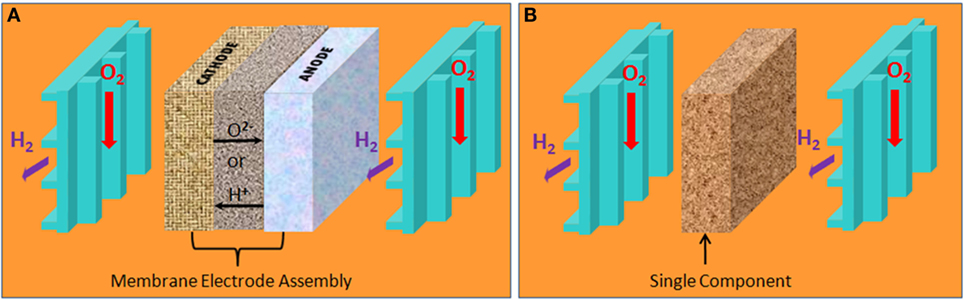
Figure 1. Structures between (A) SOFC and (B) EFFC, or called single component.
Electrolyte (Layer)-Free Fuel Cell
The Working Principle of EFFC
Traditional FC is constructed by three layers – a typical anode–electrolyte–cathode structure. The porous anode and cathode are separated by an electrolyte that is composed of dense solid oxide YSZ. The electrolyte is employed here to separate oxidant (oxygen) from reductant (fuel) and facilitate the transfer of ions (O2−), as shown in Figure 2A. The electrolyte is the key component of this structure. Unlike the SOFC structure, there is no macroscopic electrolyte in EFFCs. The structure of EFFC is a homomorphous layer that is constituted by a mixture of semiconductor and oxygen ion conductor. Its working temperature ranges from 300 to 600°C. The different working principle of EFFC has been presented by Zhu et al. (2011c, 2012).
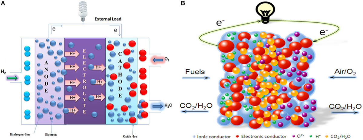
Figure 2. Comparison of working principle between (A) SOFC and (B) EFFC, or called single component.
It can be seen from Figure 2B that the EFFC fuel is oxidized and electrons are released at the anode (fuel side). At the cathode (air side), oxygen (oxidant) is reduced to oxygen ions (O2−), which combine with electrons from external circuit to generate electricity. Hydrogen is employed here to explain this electrochemical process of the EFFC.
In proton conduction case:
At the hydrogen-contacting side:
At the air (O2)-contacting side:
In oxide ion conducting case:
At the hydrogen-contacting side:
At the air (O2)-contacting side:
It is also common that the single layer may conduct both proton and oxide ions, in this case:
At the hydrogen-contacting side:
At the air (O2)-contacting side:
To all the above cases, the overall electrochemical reaction in the EFFC is the same as the common FC process:
The electrochemical process of FC can be further construed as H+ transfering from anode to cathode or as O2− migrating from cathode to anode. Transportation of O2− in traditional SOFC occurs at the electrolyte between anode and cathode. More specifically, ionic conduction can be enhanced and conducted on the particles’ surface (Veldsink et al., 1995; Suzuki et al., 2005), which is used in the EFFC device with co-ionic H+/O2− transport.
This device is named as EFFC according to the new principle. The preparation technology of EFFC is very simple. Only one component is required, which can be fabricated by the mixture of electrode (anode and cathode) and electrolyte, the so-called “Three in one,” highlighted by Nature Nanotechnology (Zhu, 2011). Different from the traditional SOFC constructed by three-layer anode–electrolyte–cathode, this new device with single component/layer can effectively convert fuel to electricity.
Advantages of EFFCs
Electrolyte (layer)-free fuel cell is a new energy conversion device showing many advantages that cannot be obtained by traditional SOFC since their operation mechanisms are different (Zhu, 2011, Zhu et al., 2011d, 2013a; Fan et al., 2012, 2013). In brief, some special merits of EFFC can be summarized as follows:
(i) The manufacturing cost is significantly reduced due to its simple structure and preparation method.
(ii) The interfaces of the electrolyte/the anode and the electrolyte/the cathode contribute to major polarization losses in the traditional three-layer structure. In addition, the three-layer device requests strict thermal compatibility and chemical stability among the anode, electrolyte, and cathode, which have different material components. These present a serious SOFC technology challenge resulting in high cost as well. However, there is only one layer in the EFFC. Hence, losses or thermal stress problem from the interface can be avoided here. This ensures the long-term stability of the EFFCs.
(iii) Electrolyte (layer)-free fuel cells fabricated by multi-functional nanocomposite materials include oxygen ion conductor and semiconductor. Ionic conductivity of the cell materials is enhanced greatly for oxygen ion conducts on the surface of the cell and in itself, simultaneously. Meanwhile, there exists a synergistic effect established among the ions, electrons, holes between n-type or p-type semiconductor, and oxygen ion conductor. It helps to prevent short-circuit current and improve ionic conductivity of the single cell. This directly reduces the working temperature of the cell and provides a chance for introducing a wide range of materials.
Technical Developments on EFFCs
“Three in one” single layer materials are the key to realize the EFFCs with semiconductor-ion conductivities, which can integrate all anode, electrolyte, and cathode functions into one. In particular, a single layer is constituted by semiconductor materials (n-type or p-type) and oxygen ion conductor composite materials (Zhu et al., 2011e). At present, exploring new multi-function nanocomposites are one of the main research activities of EFFCs.
Materials for EFFCs
At present, most of the EFFC materials are based on composite types consisting of two types of constituent materials, i.e., (1) oxide ionic conductors, e.g., Sm2O3-doped CeO2 (SDC) or Gd2O3-doped CeO2 (GDC) and various ceria-based composites and (2) semiconducting materials, e.g., various transition element metal oxides, e.g., Ni, Cu, Fe, Zn, etc., and their complex or composite types. Recent research shows that the electrochemical performance strongly depends on the properties of the constituent materials, stoichiometric proportions, compositions between the constituent ion and semiconductor, their morphology and microstructure as well as experimental conditions.
Oxide Ion Conductors
Sm2O3-Doped CeO2. At present, chemical co-precipitating method and sol–gel method are mainly carried out in the preparation of SDC. The SDC powder materials within nanoscale were synthesized by one step co-precipitation method (Zhu et al., 2011b). The raw materials of Ce(NO3)3⋅6H2O and Sm(NO3)3⋅6H2O were used (Xia et al., 2012) to prepare the SDC powder materials. In sol–gel process, both ceria and samarium nitrate hydrates formed a mixture solution of Ce(NO3)3⋅6H2O and Sm2O3, the solid citric acid was added into with vigorous stirring at 60–70°C until turning to the gel. The gel was sintered at 800°C to obtain the SDC powder materials by grinding.
Gd2O3-Doped CeO2. Apart from SDC, GDC is another material for EFFC. The GDC powder materials were obtained by using carbonate co-precipitation method (Zhu et al., 2011a). Ce(NO3)3⋅6H2O and Gd(NO3)3⋅6H2O (Ce3+:Gd3+ = 9:1) were first dissolved in deionized water to form a mixed solution. Then, Na2CO3 was added into this solution by vigorous stirring to form white precipitate at 120°C. The precipitating precursor was further subjected to washing and drying. The GDC powder materials can be obtained after sintering it at 800°C.
Modified and Doped Nanomaterials Based on SDC and GDC. Hu et al. (2014) had prepared MgZn–SDC materials by chemical co-precipitation method. Mg(NO3)2⋅6H2O and Zn(NO3)2⋅6H2O were used in the co-precipitation process for nanometer material preparation. The cost of this material has been further reduced by introducing Mg and Zn contents. Zhu et al. (2014) had prepared GDC–KAlZn (KAZ) materials by two-step co-precipitating method. They first dissolved Ce(NO3)3⋅6H2O and Gd(NO3)3⋅6H2O(Ce3+:Gd3+ = 4:1) in deionized water to get the properly distributed mixture in solution. A 0.5M Na2CO3 solution was gradually added into the mixed solution while it was stirring at 120°C. The white precipitate was formed. Following filtrating, washing, and drying processes, a GDC precursor was obtained. In parallel, KAlZn composite was also prepared by co-precipitation method. Al(NO3)3⋅9H2O and Zn(NO3)2⋅6H2O (Al3+:Zn2+ = 4:3) were dissolved in deionized water, and K2CO3 was selected as a precipitant agent to form the co-precipitation. The GDC precursor was added and then dried at 150°C. The GDC–KAlZn (KAZ) precursor was thus obtained. After washing, filtrating, drying, and then sintering at 800°C for 4 h, the GDC–KAlZn (KAZ) nanocomposite materials were obtained.
Semiconducting Materials. Up to now, semiconductor materials (n-type or p-type) for EFFCs are selected among those transition metal oxides, e.g., NiO, CuO, FeOx, ZnO, and CoOx-doped LiNiO2 or further complex or composite metal oxide materials. The first semiconductor material, LiNiO2, was reported (Zhu et al., 2011a) by using LiOH and Ni(NO3)2⋅6H2O. Then, the composite was prepared by mixing semiconductor materials LiNiO2 with GDC to fabricate the EFFC device. The maximum power output had reached 450 mW/cm2 at 550°C. Next, LiNiZn-oxide was processed and adopted by sintering Li2CO3, NiCO3⋅2Ni(OH)2⋅6H2O, Zn(NO3)2⋅6H2O via a solid-state reaction. Then, the semiconductor material LiNiZn-oxide was mixed with GDC to fabricate the EFFC. The maximum power outputs reached 300–600 mW/cm2 at 450–550°C. The maximum output power could reach 700 mW/cm2, when it was further doped by the oxidation–reduction catalyst Fe (Zhu et al., 2011b). The LiNiZnO2−δ–SDC composite materials achieved the maximum power output of the EFFC device with up to 600 mW/cm2 at 550°C (Zhu et al., 2011c). The total conductivity of LiNiZnO2−δ–SDC-mixed materials of ion conductor and semiconductor is up to 0.1–1 S/cm.
The ceria–carbonate materials were also used to get semiconductor-ion single layer materials. The maximum power output of EFFCs could reach 700 mW/cm2 at 550°C (Zhu et al., 2011e) by mixing LiNiCuZnFe-oxide and Na2CO3–SDC (NSDC) composite. The maximum power output of EFFC obtained by mixing LiNiCuSr-oxide and MgZnDC, according to a certain mass ratio, can reach 600 mW/cm2 at 550°C. Its open circuit voltage (OCV) is up to 1.02 V at the same temperature (Hu et al., 2014). Xia et al. (2011) has developed Sr2Fe1.5Mo0.5O6-δ (SFM) and NSDC in a certain mass ratio as the single layer material for the EFFC. They reported that to achieve the best device performance the electronic and ionic conductivities must be closely matched, so 30% mass of SFM was able to achieve the best performance of the maximum power output of 360 mW/cm2 at 750°C. This result is in agreement to the earlier studies as reported by Xia et al. for the SDC–LiNiZn-oxide single layer conductivities by adjusting the manipulation of concentration rations of ionic SDC to electronic conductors LiNiZn-oxide. They found that the single layer containing 30% mass of LiNiZn-oxide exhibits an almost uniform distribution of the two constituent components to establish a balance between the ionic and electronic conductors (Xia et al., 2012). Hei et al. (2014) investigated a composite of a perovskite oxide proton conductor (BaCe0.7Zr0.1Y0.2O3−δ and BCZ10Y20) and alkali carbonates (2Li2CO3:1Na2CO3 and LNC). The cell shows a maximum power density of 957 mW/cm2 at 600°C with hydrogen as the fuel and oxygen as the oxidant. The summary of the typical performance demonstrated by various EFFCs are presented in Table 1.
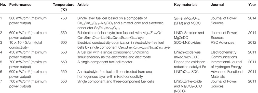
Table 1. Overview of EFFC performances.
Critical Issues on EFFC
The first critical issue is to address whether penetration of the fuel (H2) and oxidant (air) through the single layer material causes any electrochemical leakage due to H2/O2 thermal combustion. In this case, first, the security of the EFFC is of concern; the second is the electronic short-circuiting problem, by using the homogenously mixed semiconductor-ionic single layer material instead of the purely ionic-conducting electrolyte layer between the anode and cathode.
Non-Potential Safety Hazard
A separate layer of dense electrolyte is crucial for traditional FC. However, the dense electrolyte is not a must as long as it is gas tight, which can prevent gas penetration through it. Here, a major question is concerned: can oxygen and hydrogen pass through the porous single layer device and react directly to cause electrochemical leakage and potentially an explosion? The feasibility of eliminating the potential of explosion is a must for EFFC commercialization. Security level is determined by operating conditions, porosity, catalytic activity, and other features of EFFC. Liu et al. (2012) developed a dynamic model of anode and cathode reactions based on electrochemical impedance spectroscopy (EIS) to assess the performance of EFFCs. The security issue had been analyzed by using the single layer EFFCs by supplying the oxidant and fuel under the situation of open circuit conditions and operating conditions, respectively. The experimental and theoretical results show that the safety of EFFC is guaranteed. Assuming that porosity is equal to 0.5, define the torsion resistance τ is ϵ/τ = ϵ1.5, under a standard atmospheric pressure. The reaction depth of anode is 5.3–1.0 × 10⁻⁵ m and cathode is 1.4–0.25 × 10⁻⁶ m when the current is changed from 100 to 2000 mA⋅cm−2, as shown in Figure 3.
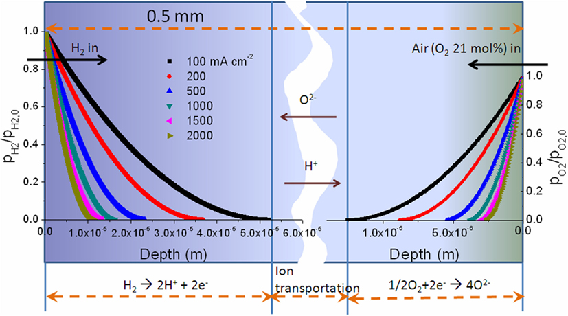
Figure 3. The curve about the depth of fuel side and air side changes, if the current changes under different current conditions; the porosity is equal to 0.5 and the thickness of the single cell is equal to 0.5 × 10⁻³ m. [Permission from Liu et al. (2012). Available from: http://pubs.rsc.org/en/Content/ArticleLanding/2012/RA/c2ra20694c].
The effect of porosity on the reaction depth is given in Figure 4. The reaction depth of O2 is in the range of 0.6–1.4 × 1.0−6 m with the porosity of 0.2–0.5. For H2, it is in the range of 2.1–5.3 × 1.0−5 m. It is shown that the reaction depth, both of H2 and O2, increase with porosity. However, all of them are far below the thickness of EFFC, which is in the microscale/10−3 m level. It is decisively proven that there is no risk of explosion under the given operating conditions.
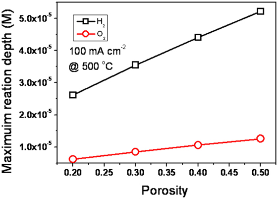
Figure 4. The effect of porosity on the reaction depth in the EFFC device. [Permission from Liu et al. (2012). Available from: http://pubs.rsc.org/en/Content/ArticleLanding/2012/RA/c2ra20694c].
Therefore, the EFFC security level is very high according to the calculations. In addition, there is a quenching distance so that the explosion cannot occur if the distance between the oxygen and hydrogen molecule is smaller than a certain separation distance. According to Janicke et al. (2000), this quenching distance is 1 mm. However, EFFC is a device constructed in basis of nanostructure. Its pore diameter is up to dozens of nanometer. The maximum micro-distance between the oxygen and hydrogen is far less than the quenching distance in a millimeter level. Hence, it is impossible to explode, even though they have met inside the EFFC device.
Short-circuit Issue and Rectification Effect
Electrolyte (layer)-free fuel cell worked as electron-blocking layer. Does electron produced from fuel side pass through the EFFC single layer device and arrive to the air side? Hence, is there a short-circuit or electrochemical leakage current? As reported in literature, OCVs of the EFFC are higher than that using the pure ionic ceria, e.g., SDC electrolyte FC. These results do not support the existence of the short-circuit current.
The rectification effect for the junction was observed for the EFFC device, which is clearly seen in the measured I–V curve when applying a bias voltage within –5 to +5 V range, as shown in Figure 5. All measurements were taken under the device OCV (open circuit condition) by supplying H2/air. The rectification effect is decreased with increasing the ionic component of NSDC. These results provide evidence that the SJFC single layer device shows the junction barrier in the presence of the constituent semiconducting material phase in the single layer device.
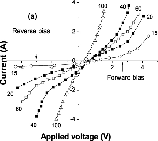
Figure 5. The device I–V measured for the SJFC devices with various compositions under applied bias voltages. wt% represents the percentage of NSDC in NSDC–LCN composite, wt = 16, 20, 40, 60, 100. [Permission from Zhu et al. (2015). Available from: http://onlinelibrary.wiley.com/wol1/doi/10.1002/aenm.201401895/full].
The single layer is constituted by semiconductor-ionic material acting as an electron-blocking layer. Actually, under the FC conditions, supplying the H2 and air, respectively, from both sides of the single layer device, there will form an n-type conducting zone in H2-contacting side, and p-type conducting zone in the air side because the semiconducting transition metal oxides possess amphoteric properties, i.e., the transition metal oxide can behave with n-type conductivity in reducing atmosphere and as p-type conductor in oxidant environment due to their defect properties (Singh et al., 2013). In this situation, a spatial n–p junction could be established, after the fuel and oxidant were supplied over the single layer device. Hydrogen is decomposed into protons and electrons on the surface of n-type semiconductor when inserting the H2 and O2 into the device. Meanwhile, oxygen receives electrons and forms oxygen ion at the surface of p-type semiconductor. More removable negative and positive charges are generated in areas of n-type and p-type semiconductor nanoparticles, respectively. A dynamic space-charge region may be re-formed between them and then internal electric field is generated similar to the traditional p–n junction. The space-charge region has two functions. The first is maintaining the electro dynamic potential of EFFC to ensure the output of electricity. The second is generating p–n junction, which can prevent electron produced at fuel side migrating to air side. It can also prevent the short-circuit current. Thus, the scientific principle is similar to solar cell.
There is still something unique for this single layer FC when compared with solar cell. Also, p–n junction is dynamic in EFFC, but static in solar cell. Spatial distribution of p–n junction is dependent on the composition of the atmosphere. We will give a more complete description about EFFC, including synergy problems of electron, ion, hole and proton, and the dynamic distribution of p–n junction, by updating the latest development in these regards.
Latest Progress on Scientific Studies of EFFCs
The invention of EFFC initiated a new scientific research frontier. However, the understanding of the electrochemistry in the existing FCs is not explicit, e.g., a key issue is how to prevent the electron passing through the device without using the electrolyte separator. The second issue is how to avoid short-circuit and electrochemical leakage when the mixing semiconductor and ionic-conducting layer are both introduced into the single layer. It is known that the mixed ionic and electronic conductors (MIECs) developed for SOFCs cannot replace the electrolyte. Otherwise, the short-circuiting problem will cause serious device OCV and power output losses (Eguchi et al., 1992; Riess et al., 1996; Shen et al., 2014). The true situation in the EFFCs is very different from the MIEC behavior, because the EFFC does not show OCV loss in a proper composition range of doped ceria ionic materials and semiconductor compared to the pure ionic-doped ceria electrolyte device, which usually exhibits rather lower OCV of 0.85–0.9 V due to the ceria-based electrolyte reduced electronic conduction. It was overcome in EFFCs using the doped ceria mixed with semiconductor materials. In our latest development, we have used the Sm-Ca co-doped ceria (SCDC), which has a high O2− conductivity of 0.12 S/cm at 700°C (Banerjee et al., 2007) and perovskite La0.6Sr0.4Co0.2Fe0.8O3−δ (LSCF), a p-type semiconductor that is one of the most promising SOFC cathodes due to its decent electrocatalytic properties for redox reactions (Esquirol et al., 2004), high electrical (p-type) conductivity, e.g., 230 S/cm at 900°C (Jiang, 2002) as well as good oxygen ion conductivity (0.1 S/cm at 800°C) (Kostogloudis and Ftikos, 1999).
Figure 6 shows typical I–V and I–P characteristics for this device compared to the pure ionic-doped ceria electrolyte device, which was fabricated using conventional FC anode/electrolyte/cathode configuration. It can be seen from Figure 6 that the OCV increased from pure ionic conductor SCDC electrolyte device 0.85 V up to 1.1 V at 45% LSCF:55% SCDC. Increasing the weight ratio of LSCF does not cause the OCV and power loss but increased significantly from pure SCDC at 300 mW/cm2 up to 496 mW/cm2 at 40% LSCF:55% SCDC. Though the OCV is somewhat lower than 0.94 V, it is still higher than that of the SCDC fuel cell 0.85 V, and the power output of the device with 55% LSCF: 45% SCDC raises to 798 mW/cm2, see Figure 6. These facts, excluding the SCDC case, are in strong disagreement to the MIEC, which would have acted as a membrane instead of the electrolyte, and would cause significant losses in both voltage and power of the assembled device (Eguchi et al., 1992; Riess et al., 1996; Shen et al., 2014). This has been also proved by using the SCDC electrolyte due to its MIEC behavior in FC environment. But in the LSCF–SCDC membrane, we can see clearly that the incorporation of electronic (hole) conduction into the SCDC to form the semiconductor-ion membrane resulted in much better performance. It indicates a completely new phenomenon because of the unique LSCF–SCDC materials, which may be defined as a new type of functional semiconductor-ionic material. To the best of our knowledge, the semiconductor-ionic material has not been reported in literature so far.
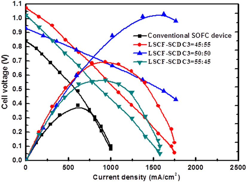
Figure 6. Typical I–V and I–P characteristics for LSCF–SCDC fuel cells in comparison to the fuel cell using the ionic SCDC electrolyte.
Understanding the scientific principle, the underlying processes have been recently investigated. The device is activated by fuel. Charge carrier (e−) is activated by fuel. When a proton (H+) is formed, an electron is produced at the same time. Negative and positive charges are generated on the surface of air side and fuel side, respectively. The junction between them becomes depleted of charges/carriers, i.e., non-conduction. Consequently, a cell potential is generated, and electric energy can be taken out the device. The device functions based on nano-redox processes, as described by the formation of bulk heterojunction structures (BHJ). The energy band difference between the n and p semiconductors allows the charge separation at particles to prevent the electron crossing over internally to avoid the short-circuit problem (Figure 7) (Zhu et al., 2013b).
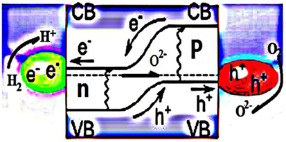
Figure 7. EFFC built on the BHJ structure and working principle. [Permission from Zhu et al. (2013a). Available from: http://www.sciencedirect.com/science/article/pii/S2211285513000827].
Also, Schottky junction has been discovered for the EFFC device. A potential or barrier can be built up at the interface between a metal and an n- or p-type semiconductor, known as the Schottky junction device (Mönch, 1994). Such device is preferably built only on p-type of semiconductor. In this case, it is a compatible anode metal, e.g., Ni or its alloy reduced from FC operation at H2 side, on the semiconductor surface, typically, p-type semiconducting oxide, e.g., LiNiO-based oxide, as reported (Zhu et al., 2015) in a Schottky type contact/junction. Such junction can directly prevent the electrons crossing over the junction to avoid the short-circuiting problem due to its built-in field or Schottky junction barrier. The working principle for such type EFFC device is presented in Figure 8.
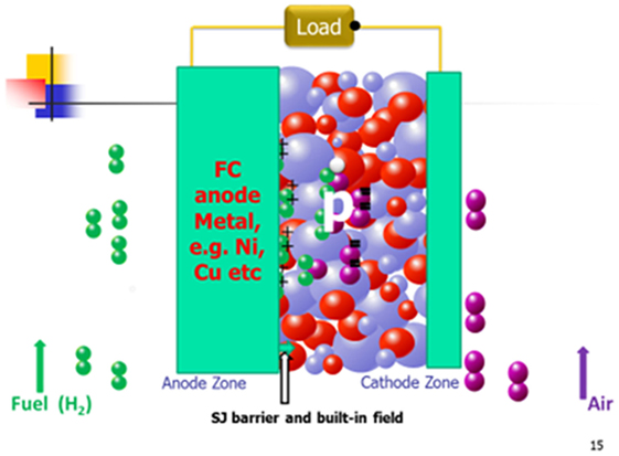
Figure 8. The EFFC with the Shottky junction barrier built on p-type semiconductor and working principle (black ball: e− charge; white ball: hole charge; green ball+: H+; purple ball−: O2−; blue and red balls simply semiconductor-ionic material).
The bilayer EFFC device was discovered before Zhu et al. (2011e). At that time, no knowledge about the semiconductor junction was possessed, though it was constructed by using LiNiCuZn (Fe)-oxide material mixed with the electrolyte, Sm0.2Ce0.8O2−x (SDC), and perovskite cathode Ba0.6Sr0.4Co0.85Fe0.15O (BSCF) (p-type) mixed with SDC were employed without using the electrolyte layer. More than 500 mW/cm2 power output was achieved at 550°C, which is comparable with the performance achieved for conventional anode LiNiCuZn (Fe)/electrolyte (SDC)/cathode (BSCF) electrolyte-based FC. Now, it is recognized in retrospect as EFFC that is based on p–n junction principle, where LiNiCuZn (Fe) reduced by H2 in FC operation forms the n-conducting layer, and thus the bilayer is actually the n–p device configuration. It is well known that p–n junction forms the depletion zone, which can prevent the electronic conduction only in one direction transport, i.e., diode effect (Constantinescu et al., 1973). The working principle for such type EFFC device is presented in Figure 9.
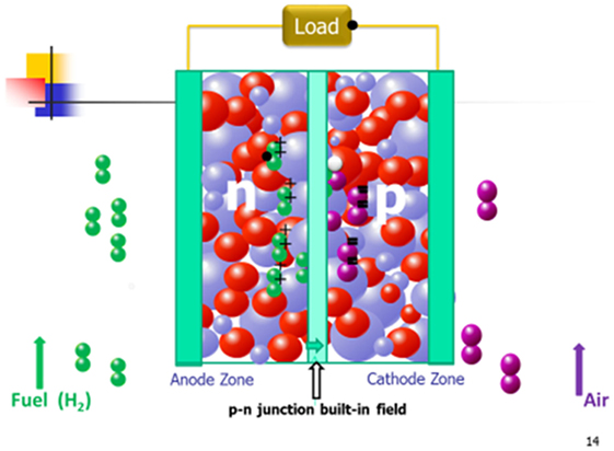
Figure 9. p–n junction type EFFC working principle (black ball: e− charge; white ball: hole charge; green ball+: H+; purple ball−: O2−; blue and red balls simply semiconductor-ionic material).
The scientific principle and underlying processes can be further understood by combining semiconducting and energy band theories. Using the LSCF–SCDC device case as the example, the energy band alignment between the LSCF and NCAL can block the electron in anode injecting into LSCF. Such well-aligned band level enables the creation of a new mechanism to prevent the semiconductor-ionic membrane device from short-circuiting and promote charge flows, and the ion transport and charge transfer more directly rather than the use of the electrolyte separator in the FC. On the other hand, the NCAL can be reduced at the anode side, to form Ni–Co metal surface; thus, a Schottky junction may be established between the metal layer and semiconductor material LSCF. The built-in field directs from the metal to LSCF (p-type), which can prevent the electrons passing through the interface between metal/LSCF–SCDC and hence establishes the device OCV. Moreover, the built-in field can actually promote the O2− across over the junction, i.e., at the anode zone. Differing from the conventional FCs, the working principle here is unique in combining semiconductor physics and electrochemistry.
Opportunities and Challenges for EFFC
Reviewing the history of the FC for over 170 years, basic technology and breakthrough are not enough to conquer the technical challenges, hence delaying the commercialization. Eventual barrier is caused or limited by the materials and the three-layer device structure. The appearance of EFFC could be not only a breakthrough but also a revolution in the FC sector. First, we overcome the inherent model that ionic conduction only happens in the electrolyte. The nanocomposite porous super ionic conduction material is built where ions can conduct both in the internal and on the surface to make it fast in transport and charge transfer to realize effectively the redox reaction for power generation. Second, the latest EFFC developments have realized much better power output that that from traditional structure SOFCs.
Electrolyte (layer)-free fuel cell was invented in 2010 and provides a new direction for FCs and SOFCs with new commercialization opportunity. It was selected as research highlight on Nature Nanotechnology in 2011 and named as “three in one” (Zhu, 2011). Introducing FC with high efficiency, zero/low emission and low noise into applications early and in large scale is of great importance. It is not only the demand of energy crisis but also for addressing environmental and low carbon emission issues. New science and energy technologies are urgently needed. EFFC semiconductor-ionic materials that can integrate FC all anode, electrolyte, and cathode functions have been invented and developed successfully. It has great potential in the competition of market issues. It is estimated that a cost of 100$/kW is feasible. The EFFC science and technology are expected to have wide application, e.g., other fuel cell technologies, not only for SOFCs, but also for other electrochemical devices, Fe–air, Al–air, Li–air batteries etc., super-capacitor, electrolysis, photoelectrochemical devices etc. It will exert great influence on the science, technology, and economy.
Conclusion
Electrolyte (layer)-free fuel cell is a new energy device and the overall function of generating electricity is done in an analogous way to a FC. It can bring high power efficiency as theoretical calculation and further expectation. On the other hand, it may also function for the electrolysis with high performance to electrolyze water. EFFC can remove the bottleneck from electrolyte, which used to be a barrier for commercialization.
This design of new device aims to conquer the conventional FC drawbacks, such as high cost, complex construction, and so on. The EFFC may rapidly drive FC industrialization and commercialization. The marketization of EFFCs largely depends on not only the materials but also the improvement of technology and the performance of the devices. There still remains a lot of future work that needs to be carried out. Initiating from the long-term development demanding of science and technology, research activities about EFFC is expanding.
Author Contributions
YL’s contribution of this work was to find and read the related literature and write the manuscript. Main idea of this work is from Dr. BZ, who also guided all the writing process. YC, J-SK, and BW’s contribution to this work were to modify the details. JW and YZ mainly focused on investigating the manuscript. JL’s work about this review was to draw the pictures.
Conflict of Interest Statement
The authors declare that the research was conducted in the absence of any commercial or financial relationships that could be construed as a potential conflict of interest.
Funding
This work was supported by the Natural Science Foundation of Hubei Province, major project (Grant No. 2015CFA120), the Swedish Research Council (Grant No. 621-2011-4983), the European Commission FP7 TriSOFC-project (Grant No. 303454), and the Swedish Agency for Innovation Systems (VINNOVA). One of the lead authors would also like to thank the Hubei Provincial 100-Talent Distinguished Professor grant.
References
Banerjee, S., Devi, P. S., Topwal, D., Mandal, S., and Menonr, K. (2007). Enhanced ionic conductivity in Ce0.8Sm0.2O1.9: unique effect of calcium co-doping. Adv. Funct. Mater. 17, 2847–2854. doi: 10.1002/adfm.200600890
Constantinescu, C., Goldenblum, A., and Sostarich, M. (1973). Photovoltaic effects in laterally illuminated p n junctions. Int. J. Electron. 35, 65–72. doi:10.1080/00207217308938517
Dufour, A. U. (1998). Fuel cells: a new contributor to stationary power. J. Power Sources 71, 19–25. doi:10.1016/S0378-7753(97)02732-8
Eguchi, K., Setoguchi, T., Inoue, T., and Arai, H. (1992). Electrical properties of ceria-based oxides and their application to solid oxide fuel cells. Solid State Ionics 52, 165. doi:10.1016/0167-2738(92)90102-U
Esquirol, A., Brandon, N. P., Kilner, J. A., and Mogensen, M. (2004). Electrochemical characterization of La0.6Sr0.4Co0.2Fe0.8O3 cathodes for intermediate-temperature SOFCs. J. Electrochem. Soc. 151, A1847–A1855. doi:10.1149/1.1799391
Fan, L. D., Wang, C. Y., Chen, M. M., and Zhu, B. (2013). Recent development of ceria-based (nano)composite materials for low temperature ceramic fuel cells and electrolyte-free fuel cells. J. Power Sources 234, 154–174. doi:10.1016/j.jpowsour.2013.01.138
Fan, L. D., Wang, C. Y., Osamudiamen, O., Raza, R., Singh, M., and Zhu, B. (2012). Mixed ion and electron conductive composites for single component fuel cells: I. Effects of composition and pellet thickness. J. Power Sources 217, 164–169. doi:10.1016/j.jpowsour.2012.05.045
Hei, Y. F., Huang, J. B., Wang, C., and Mao, Z. Q. (2014). Novel doped barium cerate-carbonate composite electrolyte material for low temperature solid oxide fuel cells. Int. J. Hydrogen Energy 39, 14328–14333. doi:10.1016/j.ijhydene.2014.04.031
Hu, H. Q., Lin, Q. Z., Zhu, Z. G., Zhu, B., and Liu, X. R. (2014). Fabrication of electrolyte-free fuel cell with Mg0.4Zn0.6O/Ce0.8Sm0.2O2-δ-Li0.3Ni0.6Cu0.07Sr0.03-O2-δ layer. J. Power Sources 248, 577–3581. doi:10.1016/j.jpowsour.2013.09.095
Janicke, M. T., Kestenbaum, H., Hagendorf, U., Schuth, F., Fichtner, M., and Schubert, K. (2000). The controlled oxidation of hydrogen from an explosive mixture of gases using a microstructured reactor/heat exchanger and Pt/Al2O3 catalyst. J. Catal. 194, 282–293. doi:10.1006/jcat.2000.2819
Jiang, S. P. (2002). A comparison of O-2 reduction reactions on porous (La,Sr)MnO3 and (La,Sr)(Co,Fe)O-3 electrodes. Solid State Ionics 146, 1–22. doi:10.1016/S0167-2738(01)00997-3
Kostogloudis, G. C., and Ftikos, C. (1999). Properties of A-site-deficient La0.6Sr0.4Co0.2Fe0.8O3-δ-based perovskite oxides. Solid State Ionics 126, 143–151. doi:10.1016/S0167-2738(99)00230-1
Liu, Q. H., Qin, H. Y., Raza, R., Fan, L. D., Li, Y. D., and Zhu, B. (2012). Advanced electrolyte-free fuel cells based on functional nanocomposites of a single porous component: analysis, modeling and validation. RSC Adv. 2, 8036–8040. doi:10.1039/c2ra20694c
Mönch, W. (1994). Metal-semiconductor contacts: electronic properties. Surf. Sci. 299-30, 928–944. doi:10.1016/0039-6028(94)90707-2
Riess, I., Gödickemeier, M., and Gauckler, L. J. (1996). Characterization of solid oxide fuel cells based on solid electrolytes or mixed ionic electronic conductors. Solid State Ionics 90, 91–104. doi:10.1016/S0167-2738(96)00355-4
Shen, S. L., Yang, Y. P., Guo, L. J., and Liu, H. T. (2014). A polarization model for a solid oxide fuel cell with a mixed ionic and electronic conductor as electrolyte. J. Power Sources 256, 43–51. doi:10.1016/j.jpowsour.2014.01.041
Singh, K., Nowotny, J., and Thangadurait, V. (2013). Amphoteric oxide semiconductors for energy conversion devices: a tutorial review. Chem. Soc. Rev. 42, 19611. doi:10.1039/c2cs35393h
Suzuki, T., Jasinski, P., Petrovsky, V., Anderson, H. U., and Dogan, F. (2005). Impact of anode microsturcture on solid oxid fuel cells. J. Electrochem. Soc. 152, A527–A531. doi:10.1149/1.1858811
Veldsink, J. W., van Damme, R. M. J., Versteeg, G. F., and van Swaajj, W. P. M. (1995). The use of the dusty-gas model for the description of mass transport with chemical reaction in porous media. Chem. Eng. J. 57, 115–125. doi:10.1016/0923-0467(94)02929-6
Xia, D., Li, T., Jiang, L., Zhao, Y. C., Tian, Y., and Li, Y. D. (2011). Single layer fuel cell based on a composite of Ce0.8Sm0.2O2-δ-Na2CO3 and amixed ionic and electronic conductor Sr2Fe1.5Mo0.5O6-δ. J. Power Sources 249, 270–276. doi:10.1016/j.jpowsour.2013.10.045
Xia, Y. J., Liu, X. J., Bai, Y. J., Li, H. P., Deng, X. L., Niu, X. D., et al. (2012). Electrical conductivity optimization in electrolyte-free fuel cells by single-component Ce0.8Sm0.2O2-δ-Li0.15Ni0.45Zn0.4 layer. RSC Adv. 2, 3828–3834. doi:10.1039/c2ra01213h
Zhang, F. Z., and Cooke, P. (2010). Hydrogen and fuel cell development in China: a review. Eur. Plan. Stud. 18, 1153–1165. doi:10.1080/09654311003791366
Zhu, B. (2011). Nature nanotechnology research highlights. Three in one. Nat. Nanotechnol. 6, 330–330.
Zhu, B., Fan, L. D., and Lund, P. (2013a). Breakthrough fuel cell technology using ceria-based multi-functional nanocomposites. Appl. Energy 106, 163–175. doi:10.1016/j.apenergy.2013.01.014
Zhu, B., Lund, P., Raza, R., Patakangas, J., Huang, Q. A., Fan, L. D., et al. (2013b). A new energy conversion technology based on nano-redox and nano-device processes. Nano Energy 2, 1179–1185. doi:10.1016/j.nanoen.2013.05.001
Zhu, B., Fan, L. D., Zhao, Y. F., Tan, W. Y., Xiong, D. B., and Wang, H. (2014). Functional semiconductor – ionic composite GDC-KZnAl/LiNiCuZnOx for single-component fuel cell. RSC Adv. 4, 9920–9925. doi:10.1039/c3ra47783e
Zhu, B., Lund, P., Raza, R., Ma, Y., Fan, L. D., Afzal, M., et al. (2015). Schottky junction effect on high performance fuel cells based on nanocomposite materials. Adv. Energy Mater. 5, 1401895. doi:10.1002/aenm.201401895
Zhu, B., Ma, L., Wang, X. D., Raza, R., Qin, H. Y., and Fan, L. D. (2011a). A fuel cell with a single component functioning simultaneously as the electrodes and electrolyte. Electrochem. Commun. 13, 225–227. doi:10.1016/j.elecom.2010.12.019
Zhu, B., Qin, H. Y., Raza, R., Liu, Q. H., Fan, L. D., Patakangas, J., et al. (2011b). A single-component fuel cell reactor. Int. J. Hydrogen Energy 36, 8536–8541. doi:10.1016/j.ijhydene.2011.04.082
Zhu, B., Raza, R., Abbas, G., and Singh, M. (2011c). An electrolyte-free fuel cell constructed from one homogenous layer with mixed conductivity. Adv. Funct. Mater. 21, 2465–2469. doi:10.1002/adfm.201002471
Zhu, B., Raza, R., Qin, H. Y., and Fan, L. D. (2011d). Fuel cells based on electrolyte and non-electrolyte separators. Energy Environ. Sci. 4, 2986–2992. doi:10.1039/c1ee01202a
Zhu, B., Raza, R., Qin, H. Y., and Fan, L. D. (2011e). Single-component and three-component fuel cells. J. Power Sources 196, 6362–6365. doi:10.1016/j.jpowsour.2011.03.078
Keywords: fuel cell, single component/layer fuel cell, electrolyte (layer)-free, research progress, solid oxide fuel cell
Citation: Lu Y, Zhu B, Cai Y, Kim J-S, Wang B, Wang J, Zhang Y and Li J (2016) Progress in Electrolyte-Free Fuel Cells. Front. Energy Res. 4:17. doi: 10.3389/fenrg.2016.00017
Received: 11 December 2015; Accepted: 12 April 2016;
Published: 02 May 2016
Edited by:
Baibiao Huang, Shandong University, ChinaReviewed by:
Weifeng Yao, Shanghai University of Electric Power, ChinaKesong Yang, University of California San Diego, USA
Copyright: © 2016 Lu, Zhu, Cai, Kim, Wang, Wang, Zhang and Li. This is an open-access article distributed under the terms of the Creative Commons Attribution License (CC BY). The use, distribution or reproduction in other forums is permitted, provided the original author(s) or licensor are credited and that the original publication in this journal is cited, in accordance with accepted academic practice. No use, distribution or reproduction is permitted which does not comply with these terms.
*Correspondence: Bin Zhu, binzhu@kth.se;
Jun Wang, wj-jw@seu.edu.cn